Ethernet MicroDock - any chance of repair?

dougg3

Well-known member
A kind person gave me a Duo 210 along with a non-working (we think) Newer Technology Ethernet MicroDock a while ago. The Duo works great. I'd like to figure out if the MicroDock can be repaired.

The ADB port on it works fine, but I can't seem to get the ethernet to work. I installed the driver and it recognizes the dock, but when I plug it into a switch or hub, the link light doesn't come on and obviously no network traffic passes through. There is a self test feature you can run in their software that will test the media access control, encoder/decoder and transceiver. The media access control and encoder/decoder pass the test, but the transceiver test fails. I don't know if anything has to be plugged in for the transceiver test to pass. I'm curious if anyone else with one of these docks would know if all three tests usually pass on a working MicroDock with nothing plugged into it.

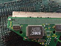
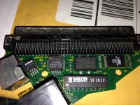
I cracked it open to look for anything obvious, but nothing really stands out. Any ideas where to even begin? Before anybody mentions it, because I know someone will, the MicroDock does not have any electrolytic capacitors :p
IMG_1666_1.JPG

IMG_1668_1.JPG


NJRoadfan

Well-known member
Try it on an old fashioned 10Mbit hub. Maybe the Ethernet chipset doesn't like auto detecting 10/100 ports. Otherwise the device is fairly simple. It has a common SMC ISA Ethernet controller, a 20mhz crystal, and the misc. parts required to build a twisted part transceiver. The Atmel chip and GAL are likely the bridge parts to connect the ISA bus chip to whatever the Duo dock port provides as a bus.


Paralel

Well-known member
Do you have another system and a crossover cable so you can try to establish a simple link over Ethernet? Most cards let you force the mode, so you shouldn't have any trouble making a modern card run in 10 duplex mode so you can check if auto-sensing is indeed the problem.


dougg3

Well-known member
Interesting ideas, thanks NJRoadfan and Paralel! I actually already tried hooking directly to a 10Mbit hub. Well, I don't have a hub, but I have a Farallon EtherWave printer adapter with two 10bT ports, I hope that's good enough. I think it's essentially a 2-port hub with a LocalTalk converter built in. Unfortunately it still doesn't create a link. I tried again just now to confirm, with both a regular and crossover cable.

I also tried setting my MacBook Pro explicitly for 10 Mbps and half duplex, and hooked it up with a crossover cable to the Minidock...still no luck. It seems like no matter what I plug in, it doesn't detect a link.

I re-ran the diagnostics to list exactly what it says:

LoopBack Tests

* Media Access Control PASS

* Encoder/Decoder PASS

* Transceiver FAIL

Cable connection test FAIL

I can't tell what chip is what. Is there a particular chip that is the transceiver, or is it all mixed together inside the SMC chip?


dougg3

Well-known member
Thanks guys! Maybe I'll start with trying to find a replacement for the SF1012 and see how that goes...I also suppose it would help for me to trace with an oscilloscope to see what the signals look like...and also test continuity...


techknight

Well-known member
SF1012 has failed. Common with a lightning strike. Its a matching transformer, you can measure the resistance of both the primary and secondary coils on both sides. if ones open, its failed.


dougg3

Well-known member
Thanks. It looks like each coil has three pins...both ends and a center tap. So I'm assuming every combination of two of the three pins belonging to a coil should show some kind of resistance. Left to right, left to center, and right to center should all have resistance. Right?

It's in-circuit, and the pins are old and don't make good contact with my multimeter, so I may need to remove the chip before I can say for certain. But I think I'm seeing some open circuits, like where left to center shows resistance but right to center and right to left both show open circuit. I'm also seeing really low resistances, but that could easily be because I'm measuring in-circuit.

I'll remove the chip and check again, but I don't think being in-circuit could cause an open reading...right? I found a source for SF1012, but they have a minimum order of $25 so I'm going to shop around to see if I can find something cheaper, or else I'll have to order 12 of these dang things and I only need one :)


dougg3

Well-known member
Well, I ended up ordering 12 of the SF1012 because I couldn't find any alternative sources. If anyone else needs some, I'll have them in stock for a while, I guess :p


dougg3

Well-known member
Yep, definitely some opens on the transformer after I got it removed.

I lifted a pad while removing it because I was being stupid.. :-( but it should be fixable, I know where the other end of the trace goes.


dougg3

Well-known member
Hehe, yeah...when I called it a chip I wasn't thinking, my bad. And I was thinking about my testing: of COURSE the resistance is supposed to be about zero. It's just a wire from one end to the other. So yeah.

Three of the four coils have a problem. One of the transformers has an open on both the primary and the secondary, and one of the transformers has an open on one of them (not sure which, don't really care). Can't wait for the new transformers to arrive so I can try it out!

I epoxied the lifted pad back to the PCB. After it has cured I will try to attach it to its trace with a bit of solder. I don't think the epoxy is going to survive the soldering iron heat, but it's worth a shot I guess. I can always run a short wire to replace the trace.

 
Last edited by a moderator:

techknight

Well-known member
Well, if the transformer is open on both the primary AND secondary, I hope the SMC IC didnt take damage from the lightning strike.


dougg3

Well-known member
Eek, that's true...well, we'll find out before long. Maybe I'll be sourcing a replacement SMC IC after this :p


Bunsen

Admin-Witchfinder-General
a common SMC ISA Ethernet controller / The Atmel chip and GAL are likely the bridge parts to connect the ISA bus chip to / the Duo dock port
How very interesting....

BTW, the Duo dock is a bridged 030 PDS like the LC series.


NJRoadfan

Well-known member
How very interesting....
BTW, the Duo dock is a bridged 030 PDS like the LC series.
This isn't all that unusual.

0681.jpg.36b616d1a0adb11f94d2741655b6f263.jpg


Above is an ISA NIC adapted for the Amiga's Zorro Bus, which is basically a direct 68k expansion bus with a DMA controller and interrupts. 3rd Parties even sold "bridge boards" the connect the passive ISA backplane in big box Amigas to the Zorro bus so ISA NICs could be used.

IDE on any platform besides the PC, is technically an ISA bus implementation (this is the case on Nubus Macs, PCI bus machines use readily available chipsets that can do DMA), only the connector is different. ISA NICs usually only require access to a 16bit wide data bus and some address lines, and occasionally an interrupt request. The logic to adapt them to a non-IBM PC bus is simple. The only thing you can't do is DMA since that requires a real x86 CPU.


dougg3

Well-known member
Well, my set of 12 SF1012 transformers arrived today! First of all, I checked with a multimeter to verify. Yes, the original one had an open on three of the four coils--the replacement chips show continuity between all three pins on each coil as expected.

Also as I suspected, epoxying the lifted pad (which was broken from its trace) back to the PCB did not work -- the epoxy was no match for the soldering iron heat. So I did something fairly difficult (for me, anyway). I scraped solder mask off the remaining trace (which is UNDERNEATH where the SF1012 would go, annoyingly), soldered a 28 gauge wire to it, and let it hang way far off the PCB. Then when I put in the replacement SF1012, I soldered the leg that goes to the missing pad onto the 28 gauge wire so it was reconnected to the trace. Then I confirmed the chip leg was reconnected and cut the rest of the wire off. It was kind of tough because too much heat would disconnect the wire (underneath the SF1012 at this point) from the trace and then I'd be screwed. But whew, it worked.

Anyway, the replacement SF1012 is on there and IT'S ALIVE! Woohoo!!!! :) Thanks again for your help Paralel, NJRoadfan, and techknight! Happy to be able to fix it, and glad the only thing wrong was the pulse transformers.

For future reference, the transceiver test seems to fail until there's a good ethernet link. So if you don't have anything hooked into the port, the transceiver test will fail. As soon as you plug it into a switch (I used a 10/100 switch) and the link light comes on, then the transceiver test passes.

 
Top