• Updated 2023-07-12: Hello, Guest! Welcome back, and be sure to check out this follow-up post about our outage a week or so ago.

Dead SWIM chip on recapped Macintosh Portable?

Hi I'm restoring a Portable and have recapped. Everything works perfectly now except as soon as the system tries to read a disk the whole system crashed.

 
A bit of research suggested the SWIM chip and some times the SWIM clock are to blame. I have a dead LC board with the same chip that I could use but I thought someone might know a bit more before I attempt a switch over.
 
 
My question is
 
Does anyone know how I would test the SWIM chip/clock and track down the cause of this issue?
 
 
A few more details and observations
 
If I try to boot from floppy (or floppy emu) it's an instant sad mac usually returning 0000000F 0000000A or in sad mac codes 'Class Code F = Exception' 'Sub Code 000A = Line 1111' 
 
If booted to the internal SCSI drive I get the bomb message with 'Bad F-line instruction' and a restart button on read, however I can't click it as the system is locked up.


Recap details
 
- All electrolytic caps were changed
 
- The board was ultrasonically cleaned with the correct solution and demineralised water
 
- Then soaked in IPA and dried with warm air
 
 
Fails in the following configurations
 
- Running on a 6V 4.5AH sealed lead acid battery with new 9V backup battery
 
- Running on an original white charger that still outputs the correct voltage, with the batteries installed as described
 
- With the original floppy drive installed
 
- With a floppy emu installed internally with the floppy drive
 
- With a floppy emu installed externally with the floppy drive
 
- With a floppy emu installed without the drive on floppy 1, 2 and external
 
 
Other notes
 
- The emu has been tested on another machine and works fine
 
- I checked the surface temp of the SWIM chip and it's running at about 30C/86F while everything else is running at about 20C/68F. 
 
- The emu does strange things when the power adapter is plugged in. Fails to 'read disks', random things on screen, can't find SD card etc. Run it on battery and it's all good again.
 
- It looked like some of the through-hole caps had been changed before but I changed them all again as the electrolytic smts hadn't been changed. I'm suspect on a few of vias C3, C6 and C2 weren't in the best condition and though I was careful I can't be sure I didn't make them worse, except that the rest of the system seems to run indicating all is ok.
 
Any help would be greatly appreciated!
 

techknight

Well-known member
2 things: 

1. Lack of voltage. probably +12V if the physical drive is having issues. 

2. if the SWIM is hotter than everything else, its guaranteed bad. they arnt supposed to get warm whatsoever. 

The failure of the SWIM IC is caused by 1 of the 2 red wires in the 4 pin battery connector loosing contact while the other remains with contact. it causes the 5V regulator to saturate and shoot the whole board with 6.2v up to 7.5v. First thing that goes is the SWIM IC. the other things that go are the 7402 and the other group of little logic ICs to the right of the CPU. 

 
Last edited by a moderator:
Thanks techknight, really appreciate that info. I'll check the voltages and harness, change out that chip and hopefully soon I can let you know how I go.

 
Hi Techknight,

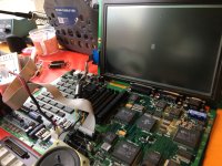
I have an almost perfect portable now! Thank you again for the advice. That was my first chip transplant and you can see it here booting from the FloppyEmu.

Can I ask some more advice? I've noticed there are still issues with power.

For example;

1) It runs well on battery but as soon as the correct adapter is in it will show significant banding through the screen which remains for a while after the charger is removed

2) If the charger is in when powered on it just hangs with the mouse working but never makes it to the flashing floppy

3) If booted on battery and then the adapter is added it will run ok but gives a sad mac randomly sometimes

4) It still gives a sad mac while waiting for a floppy maybe one out of five times

I've been reading this thread about power regulation and have downloaded the schematic but I don't have a strong background in electronics so a lot of the terminology is beyond me at the moment, though I'm willing to learn. 

As a starting point I'm wondering if you can point me to any points on the board that I should start testing based on the above behaviours?

Thanks again

IMG_3816.JPG


techknight

Well-known member
The only thing you can do at this point is adding some flux to all the components on the Hybrid IC, and then reflowing the IC with a hot air reflow gun until all the solder joints become shiny and molten, then remove the heat. 

Cap goo gets on the hybrid IC, and causes all kinds of these strange issues and the flux and reflow will ball it up and remove it. It usually works 80% of the time. If that doesnt work, then you may be SOL at this point. sometimes these weird issues can occur in the PMU but not nearly as often as the Hybrid. 

Last but not least, check the NMI and reset buttons on the side, make sure they are still electrically connected to the 2 nearby capacitors, and the 2 pullup resistors underneath, and that they ring back to 2 pins on the MISC GLU. 

if the NMI or RESET line is broken there, itll float and cause similar issues. 

 
Last edited by a moderator:

techknight

Well-known member
They will check out and thats fine, however the circuit is very poorly designed and its overly sensitive to parasitic capacitances and inductances, plus the slight increase in resistance of the traces as the cap goo gets onto the substrate and eats at it. 

 
So it looks like I'm SOL with this one for now... luckily I've got a garage full of computers to restore. I'm still pretty happy with my progress for a first try and will shelve it with notes until I learn more about electronics.

Basically after the reflow and clean it runs flawlessly on power with everything connected, but gives black bars or nothing on battery unless no floppy is connected. Without a floppy it will get to the flashing disk but now has a noise coming from the speaker. One regulator seems to have dropped to 5v on the middle pin as it should be but the others are still passing 6.5v straight through.

New question for a second portable I have, a backlit one... but only if you have any energy left. You've been very generous so far.

I recapped and cleaned it while waiting to change the SWIM chip on the first portable. It booted and ran perfectly first try after that. After a few boots and about an hour of use total it gave me a sad mac while I was playing with the control panel. Since then it's never booted again, immediate sad mac every single time.

Code is always 0000000E 00002000 which is some sort of RAM error. Any ideas what to do there? Don't even know where to start on locating the dodgy chip and finding a replacement if that's what's needed. Driving me nuts. I'm so determined to fully restore one of these things so I can enjoy one again.

IMG_2426.JPG


techknight

Well-known member
The $E code is caused by a broken trace on the R/W Line between the CPU and the GLU. You will need a patch wire and solder between the two ICs. 

that will fix it. Portables are very touchy beasts these days. I have seen a whole host of problems, and not all of them are fixable. I have a box full of parts boards, so I know. 

 
Last edited by a moderator:
Gee they must be so delicate. Does it get better from the Powerbook 100?

You know there is already a wire between those two chips so you must be spot on, it has clearly had issues there before and been repaired. I probably disturbed it or maybe another is broken. Will see.


techknight

Well-known member
If there is, then it is likely I had repaired this board in the past and it made its way to you somewhere in its journey. If the wire is white or blue, it was one that I had seen in the past. 

 
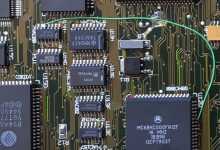
Ok so the wire wasn't actually between those two chips, I was mis-remembering but here's a pic. Green wire but look familiar? In the time I had with it while it was working after the recap I worked out it was from a university in Sydney Australia and looked like it hadn't been opened since it died in 1995. Still had the original caps and a working original adapter.

I traced the R/W line from the CPU to two pins, one on the video chip marked in red and pin 2 on U13E. Both check out. From there I found the pinout for the 74AC10 and followed it out pin 12 and around the board a bit but ultimately some of the vias go through to under other chips where I can't follow along anymore. 

Do you know the CPU GLU pin that R/W pin is meant to go to? Seems it's a lot harder to find the data sheets for the VLSI chips, I guess they were custom?

Screen_Shot_2017-12-21_at_2_32.20_pm.png


techknight

Well-known member
Your reading the video glu. You need to look at the OTHER chip, the main GLU. CPU GLU. 

I can give you a physical pin number in a bit. 

 
Last edited by a moderator:
Thanks for looking that up for me. Unfortunately that pin checks out. Not that it's helped but I did find a broken trace to the Write Enable pin on one of the RAM chips, and another on another chip between an I/O pin and 74AC245. I'll have to keep hunting around


techknight

Well-known member
Yeah you've got a broken read-write line somewhere. It may not be between those 2 ICS but it's somewhere. Write enable is also controlled by the same read-write from the CPU bus

 
Top