You are using an out of date browser. It may not display this or other websites correctly.
You should upgrade or use an alternative browser.
You should upgrade or use an alternative browser.
Cloning the Farallon MacRecorder
- Thread starter Tashtari
- Start date
Tashtari
PIC Whisperer
Because of the way the 26LS32 (receiver) in the Mac is wired for HSKi, with V- connected to ground, unless I'm very much mistaken, V+ has to go below ground in order for the Mac to register it as a logic low. Unfortunately, none of the driver chips I've seen actually do that. Makes sense, as it's harder to do and not usually necessary as RS-422/423/485 signals are usually carried in both positive and negative form - Macs just took a shortcut and wired HSKi as single-ended.Does differential input require ±V or can it accept +V and 0V? But you only need it for output for HSKi.
cheesestraws
Well-known member
Unfortunately, none of the driver chips I've seen actually do that.
They're not required to. Nominal voltages are 0 and 5V. But they are required to play nicely with common mode voltages in quite a wide range. In LT, of course, this is all moot because it's isolated, so you can choose whatever measurement point you like.
Macs just took a shortcut and wired HSKi as single-ended.
HSKi isn't part of the standard anyway - IIRC the entire scope of the standards is the differential pair and the electrical behaviour thereof.
Tashtari
PIC Whisperer
I feel like we're straying from the topic a bit here, and I'm afraid I'm confusing the issue by talking about RS-232/422/423/485. To clarify, what I'm looking for is a circuit that I can connect to a 4 MHz (or so) 0V/5V square wave output that will turn it into a -5V/+5V square wave (exact +/- voltage negotiable). I'm told it can be done with a pair of transistors, but that in itself isn't enough information for me to build a circuit, I actually need things like part numbers.
Tashtari
PIC Whisperer
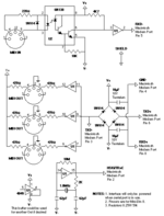
There's this one:Don't the serial port MIDI interfaces drive the 31250 baud clock through HSKi? If there's a schematic for that you can look at how it drives it.

I'm not sure how well I understand where V+ and V- are coming from... but I'm finding this approach potentially interesting, especially since it seems like a complicated/expensive undertaking to generate -5V from +5V.
Tashtari
PIC Whisperer
Got my MacRecorder! Its protocol is really pretty simple, I was just being thrown for a loop by the fact that my SE wasn't playing nice with either the real thing or my test PIC... my writeup is here.
Notably, the clock isn't at 3.58 MHz like I expected, it's at 358 kHz, which puts it in the range of possibility to use an RS232 driver... might be more desirable to suck power off the TxD± pins and do something like the MIDI interface, though.
I've also written up a rough-out of some PIC firmware to duplicate it, targeting the PIC12F1501. With its numerically-controlled oscillator (NCO) peripheral, it's able to generate the same (within a margin of error) 358 kHz clock signal as the real thing, without needing an external oscillator. The MacRecorder protocol is so simple, I was able to implement it twice in the same PIC, sampling two analog pins and making two serial outputs in addition to the clock, which will simulate having two MacRecorders and doing stereo audio recording with them.
I've got some PIC12F1501s and a fast RS232 driver coming in my next Digikey order, so I'll be able to test things properly when they arrive. Look for a more finished product coming down the pipeline from me and @demik in the not too distant future. =)
Fizzbinn
Well-known member
Curious, does that mean for stereo it would need to connect to two serial ports (like two physical MacRecorders would to do stereo), or is there someway the serial outputs could be interleaved? ...although I suppose then it wouldn't work with the MacRecorder drivers...The MacRecorder protocol is so simple, I was able to implement it twice in the same PIC, sampling two analog pins and making two serial outputs in addition to the clock, which will simulate having two MacRecorders and doing stereo audio recording with them.
To clarify, what I'm looking for is a circuit that I can connect to a 4 MHz (or so) 0V/5V square wave output that will turn it into a -5V/+5V square wave (exact +/- voltage negotiable).
Inverting or non-inverting?
Tashtari
PIC Whisperer
Two serial ports - SoundEdit has been designed with this capability in mind in case you bought two MacRecorders. From a technical perspective, it's certainly possible to interleave samples from two channels, albeit at half the rate, but as you say, the MacRecorder software and drivers weren't designed to handle this.Curious, does that mean for stereo it would need to connect to two serial ports (like two physical MacRecorders would to do stereo), or is there someway the serial outputs could be interleaved? ...although I suppose then it wouldn't work with the MacRecorder drivers...
Honestly, for the clock, I can work with either - though having investigated the device, the requirements are a bit relaxed, they only have to be able to handle driving 358 kHz, not 4 MHz.Inverting or non-inverting?
Tashtari
PIC Whisperer
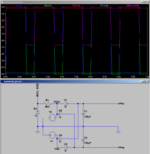
If we're taking power off TxD+ and TxD- like the real MacRecorder does, we have a positive and negative some-number-of-volts rail (on my Classic they appear to be +3V and -2.5V).Does your design have a -5V rail?
Not sure how to interpret your schematic, does it have three power supplies?
Not sure how to interpret your schematic, does it have three power supplies?
It has a positive and negative supply (V1 and V2). V3 is a clock signal.
If your rails come from the TX lines, multiply the two resistors by 5-10x to reduce current.
Tashtari
PIC Whisperer
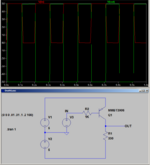
Hmm... so would this work?

Here, RA2 on the PIC is generating the clock signal, and RA5/RA4 are outputting opposite signals (so a true negative voltage isn't necessary there).
I feel like some protection circuitry is necessary in case TxD+ goes negative... a diode of some kind between TxD+ and Vcc on the PIC?
(Excuse the fact that the graphic looks like it was made on a TI-83, it wasn't, but I like the aesthetic. =D)
Tashtari
PIC Whisperer
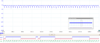
Tried building and running this circuit with a test PIC (not the 12F1501 yet) and it doesn't seem to be having quite the desired effect:

The scope is reading the value of HSKi from the collector leg of the transistor, the logic analyzer's HSKi line is reading the value of RA2. The fast rise of HSKi is coincident with RA2 going low, maybe I overdid it with one of the resistor values?

The scope is reading the value of HSKi from the collector leg of the transistor, the logic analyzer's HSKi line is reading the value of RA2. The fast rise of HSKi is coincident with RA2 going low, maybe I overdid it with one of the resistor values?
Tashtari
PIC Whisperer
Aha! Switched out the 3.3 KΩ resistor with a 470 Ω resistor and the waveform actually dips below zero for a reasonable time now. The waveform is still kind of pointy at the bottom, but it works well enough to send a test sine wave to SoundEdit. Thanks @ymk ! I'd be happy to hear any suggestions how to further refine this.
I'm glad you got it working.
A circuit like this would provide that protection. It's a more stable, filtered power supply that also allows the Mac to send (on MCU_RXD). The diodes should be Schottky types:

I feel like some protection circuitry is necessary in case TxD+ goes negative... a diode of some kind between TxD+ and Vcc on the PIC?
A circuit like this would provide that protection. It's a more stable, filtered power supply that also allows the Mac to send (on MCU_RXD). The diodes should be Schottky types:

Tashtari
PIC Whisperer
A little more story... I went hunting for trouble and asked in ##electronics on Libera about how I could improve the shape of the waveform being output by the 2N3906, and we determined that the 2N3906 I was using either was defective, counterfeit, or not a 2N3906. Weird.
At @demik 's suggestion, I'm trying something new:

My hope is the 1N4148 will serve to (1) drop TxD+ a bit so that compared to TxD- it's a bit more comfortably within the PIC's recommended Vcc range and (2) protect against the case where TxD+ is negative and TxD- is positive. The advantage of this, besides lower component count, is that it shouldn't require biasing of the audio signal. I'm not sure if the balance will necessarily be correct as it depends on TxD- and TxD+ being exact opposites of one another, which we know they aren't, but I might be able to compensate for this in firmware...
Is this crazy or just crazy enough to work?
At @demik 's suggestion, I'm trying something new:

My hope is the 1N4148 will serve to (1) drop TxD+ a bit so that compared to TxD- it's a bit more comfortably within the PIC's recommended Vcc range and (2) protect against the case where TxD+ is negative and TxD- is positive. The advantage of this, besides lower component count, is that it shouldn't require biasing of the audio signal. I'm not sure if the balance will necessarily be correct as it depends on TxD- and TxD+ being exact opposites of one another, which we know they aren't, but I might be able to compensate for this in firmware...
Is this crazy or just crazy enough to work?
Similar threads
- Replies
- 22
- Views
- 3K
- Replies
- 23
- Views
- 1K
- Replies
- 2
- Views
- 413

