• Updated 2023-07-12: Hello, Guest! Welcome back, and be sure to check out this follow-up post about our outage a week or so ago.

ATX Power Supply Mod for Quadra 840av

landoGriffin

Well-known member
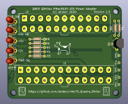
Hi all! There's some really cool stuff going on in this forum with power supply conversions to use an ATX PSU to replace a failing vintage Mac PSU. I'm curious if anyone has made a nice adapter board for the Quadra 840av power supply? 

There's lots of good information in this thread to start with (I'm assuming the Quadra 840av and PM 8100 use the same or similar power supply)


It looks like it can be done with an easy-enough cable mod.... but I like to make PCBs :)

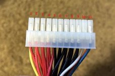
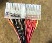
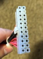
The Mac connector looks like a https://www.molex.com/molex/products/part-detail/crimp_housings/0039012220

which mates with a https://www.molex.com/molex/products/part-detail/pcb_headers/0039281223


BadGoldEagle

Well-known member
Hi there

I can’t download your gerbers right now. I’ll have a look later today. But be careful with those pinouts... The Q900 and its derivatives (950, WGS95 and WGS9150) all use a 24 pin connector (not 22!) and the pinout on this site is completely off! Please double check on your PSU before plugging anything in!!


BadGoldEagle

Well-known member
The wiring diagram looks correct for the 840.

I just downloaded your project files, it's looking really good for a first draft!

A few comments/suggestions, nothing critical:

1/ Is there a specific reason you chose an ATX20 header over a 24 pin one? PSUs with that kind of connector are getting old and I'm not sure whether you can fit a 24pin plug on a 20pin header or not. Maybe you can, I just don't know.

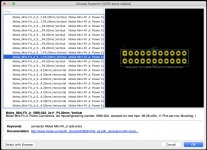
2/ The 22 pin header footprint on the Quadra side looks hand made? There is a built in Kicad footprint that looks quite similar to the one on the ATX side. I know from experience (QuadrATX 9x0 board #000) that it makes soldering those large connectors a breeze. Plus the larger the pad, the less likely it is to rip it off if you make a mistake. 

3/ Speaking of footprints and default ones, the one you used for the Softpower transistor looks a lot better than the one I used originally, but the pads might still be a tad too close together? Especially 1 and 2. I would use TO-92L-Wide just to be extra sure. 

4/ Do you really need that many VIAs for the ground plane? It's only power and you already have thermal reliefs on every GND pad... 

5/ Do you need the trace that goes from J1-Pin7 to J2-Pin19?

6/ What are the J3-6 connectors for? Just curious...

7/ There are a couple 90° angles (5V trace on back copper). Shouldn't pose too much of a problem since again this is only power. 

8/ The Q950 text should be removed (silkscreen)

9/ The silkscreen text for H1 and H4 is outside the board

10/ The resistor values for the LEDs aren't final right?

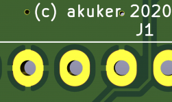
11/ Thermal reliefs could be a bit bigger

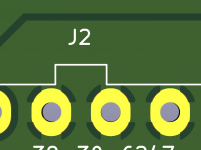
12/ J2 silkscreen inside a pad

13/ Are you planning on securing your board to the original metal casing? If so I wouldn't mix DC GND with AC earth and I'd replace the plated mounting holes with non plated ones.

14/ Just a personal preference but since the Quadra isn't using 3.3V, do you need an LED and traces for this rail? For the QuadrATX 9x0, I simply connected them to n.c.

15/ The -12V trace on the top (red) is all right, but it gets a bit too close to the 5V standby trace. The .2mm gap between them is still enough (17<30VDC) but why risk it? 

16/ The GND copper zone failed in a few places. 3D Viewer is great to see that sort of thing!
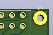
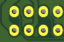
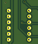
Bildschirmfoto 2020-09-17 um 17.33.36.pngBildschirmfoto 2020-09-17 um 17.33.26.pngBildschirmfoto 2020-09-17 um 17.33.14.pngBildschirmfoto 2020-09-17 um 17.33.08.png

That's all I can think of at the moment. Hope this helps!


landoGriffin

Well-known member
Holy cow! Thank you for the awesome feedback. I sincerely appreciate it!

1/ Is there a specific reason you chose an ATX20 header over a 24 pin one? PSUs with that kind of connector are getting old and I'm not sure whether you can fit a 24pin plug on a 20pin header or not. Maybe you can, I just don't know.
I should probably switch to an ATX 24pin. I originally did that for board space, but in hindsight, its probably better to use the newer plug.

2/ The 22 pin header footprint on the Quadra side looks hand made? There is a built in Kicad footprint that looks quite similar to the one on the ATX side. I know from experience (QuadrATX 9x0 board #000) that it makes soldering those large connectors a breeze. Plus the larger the pad, the less likely it is to rip it off if you make a mistake. 
I downloaded the 22 pin header from Mouser. I'm going to re-visit those connectors to double check them before I order

3/ Speaking of footprints and default ones, the one you used for the Softpower transistor looks a lot better than the one I used originally, but the pads might still be a tad too close together? Especially 1 and 2. I would use TO-92L-Wide just to be extra sure. 
Good suggestion!

4/ Do you really need that many VIAs for the ground plane? It's only power and you already have thermal reliefs on every GND pad... 
Probably not. I'm definitely not the most experienced pcb designer in the world. So, I was going for "better safe than sorry"

5/ Do you need the trace that goes from J1-Pin7 to J2-Pin19?
Nope. I added it there to reserve a good, direct ground connection while I was routing other things. But, probably not necessary.

6/ What are the J3-6 connectors for? Just curious...
Those were basically just for perfboard-type functionality, in case I needed them. I wasn't really going to use them as connectors. I just used the connector footprint, so that the holes were evenly spaced out.

7/ There are a couple 90° angles (5V trace on back copper). Shouldn't pose too much of a problem since again this is only power. 

8/ The Q950 text should be removed (silkscreen)

9/ The silkscreen text for H1 and H4 is outside the board
Good catches!

10/ The resistor values for the LEDs aren't final right?
Ya. The LEDs and resistors probably won't be populated. They're just there "in case"

11/ Thermal reliefs could be a bit bigger
Any particular ones? Or just in general?

12/ J2 silkscreen inside a pad
Good catch!

13/ Are you planning on securing your board to the original metal casing? If so I wouldn't mix DC GND with AC earth and I'd replace the plated mounting holes with non plated ones.
I hadn't really thought that far ahead yet. That's definitely a good sugestion. 

14/ Just a personal preference but since the Quadra isn't using 3.3V, do you need an LED and traces for this rail? For the QuadrATX 9x0, I simply connected them to n.c.
Nope, don't need a 3.3v LED. These won't be populated in the build. They're probably a waste of space, so I'll probably delete them.

15/ The -12V trace on the top (red) is all right, but it gets a bit too close to the 5V standby trace. The .2mm gap between them is still enough (17<30VDC) but why risk it? 
For sure. We want to keep the magic smoke inside the board.

16/ The GND copper zone failed in a few places. 3D Viewer is great to see that sort of thing!
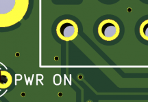
I'd double check that after I pull in your suggestions.

Thank you so much!! I really appreciate the feedback!


BadGoldEagle

Well-known member
I downloaded the 22 pin header from Mouser. I'm going to re-visit those connectors to double check them before I order
Bildschirmfoto 2020-09-17 um 19.23.58.png

11/ Thermal reliefs could be a bit bigger
Any particular ones? Or just in general?
The high amperage ones (Mini-Fit Jr headers). The rest's fine. For example:

Bildschirmfoto 2020-09-17 um 19.26.58.png

I set the thermal spoke (select copper zones and hit E for properties) to 1.4mm on mine. 

Bildschirmfoto 2020-09-17 um 19.30.35.png

I'm definitely not the most experienced pcb designer in the world.
I'm definitely not that either. Just happy to help. I learned A LOT these last few months and the QuadrATX 9x0 is my first PCB project.  :)


landoGriffin

Well-known member
I took the plunge and ordered some from JLCPCB tonight! Thank you again for the feedback @BadGoldEagle

I hope I'm not stepping on anyone's toes by calling it a mAcTX! Its such a cool name, I wanted to tag along :)  

image.png


landoGriffin

Well-known member
Woohoo!!! It works! It took a little fiddling to get things working. After I cut off the LEDs, things seemed to work much better. But, I'm not sure if that's because of the LEDs, or because of something else I did. Ultimately, the LEDs don't matter, so I'd recommend anyone who uses this in the future should just skip those.

16015938d224dbe860cfb8225fc5a75c.jpeg.0a80b4d013279053d94f2455630f5a19.jpeg
19c72f183b283ba40f280280a675c0d7.jpeg.77609e586b68b49ef8bbae7edc592869.jpeg
f41d5b113e264d7782ec55603f745329.jpeg.d35ae650388b009547778be8860b21e0.jpeg


Thanks again @BadGoldEagle for your review comments!

As far as projects go, this one has to have the least glamorous pictures :)  

If anyone else out there needs one of these boards, just PM me and I'd be glad to share. I only needed one, but they came in a package of 5.

 
@landoGriffin I recently got a Quadra 840AV, and although the PSU works fine, I want to be proactive in case it dies on me. Do you have any more pictures of how you assembled the PSU, and what ATX PSU do you recommend? Also, did you use the original fan or did you replace that too?
 
Top