• Updated 2023-07-12: Hello, Guest! Welcome back, and be sure to check out this follow-up post about our outage a week or so ago.

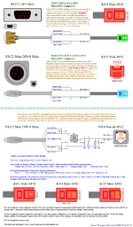
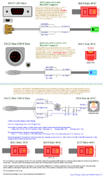
Anybody want to look over my PhoneNET helper image?

Mk.558

Well-known member
Something I've had on my mind for awhile that will go in the next update of the Guide. Have a look and tell me what you think.

I do have two questions: Is there really a +/- fixed polarity on RS422 differential pairs? Couldn't it vary from one pin to the next, like at T+56 Pin 2 is 3.13 volts measured to ground and Pin 3 is -0.9v, but at T+118 it might be the other way around?

Also I'm not sure if I can track down the resistance values they used across the balancing resistors for the DE-9 PhoneNET boxes. Can't remember even seeing one. If you have one it's easy to hook up a DMM to measure across 4 and 8, then 5 and 9. I got 1K ohms on my Mini-DIN-8 box, but the patent says "it depends".
xm5v89e3.png

EDIT: updates: add text to first column saying this is for a 512K and 512Ke only
 

NJRoadfan

Well-known member
The DE-9 port was much more commonly used for LocalTalk on the LaserWriter/LaserWriter Plus. The Kinetics FastPath 4 also uses the DE-9.
 

tashtari

PIC Whisperer
Maybe they should have more in them, but I cracked open one of my PhoneNet dongles a while back and the only thing inside it was a transformer, no resistors or varistors. (Though it's possible they're built into the transformer unit?)

Also, I wonder if CapNet is worth a mention - it might be safer than directly connecting directly to the pins of the RS422 port.

Footnote: Kudos to you for correctly saying "DE-9" instead of "DB-9", folks getting this wrong is one of my pet peeves. =D
 

tashtari

PIC Whisperer
Also, open question: will any 1:1 transformer work in a homemade PhoneNet dongle? I haven't looked at the PhoneNet patent, but the LocalTalk dongle specification in Inside AppleTalk lists a bunch of characteristics for the transformer, and I'm not enough of an electrical engineer to know which ones matter...
 

Andy

Well-known member
You have the three plug images at the bottom labeled as 2P2C, 4P4C, and 6P6C but the jack listing below all say 6 position. Aren't all of the plugs 6P? I honestly don't know the right answer, but I am confused ;)
 

cheesestraws

Well-known member
I do have two questions: Is there really a +/- fixed polarity on RS422 differential pairs?

This isn't how differential pairs work. No, polarity is not fixed: as you surmised, the voltages on the lines vary over time. The + means that when the + line is positive, the signal being transmitted is a high. When the + line is negative, the signal being transmitted is a low. The - line is really an "inverting line" rather than a negative line, and it always does the opposite.

In other words, what you are looking at is:

output = voltage of pos line - voltage of negative line

The difference here is why it's called a differential pair. Let's look at the examples above. When the positive line is at 2.5V and the negative line is at -2.5, output = 2.5 - -2.5 = 5V, so high. When it's the other way round, it's -2.5 - 2.5 = -5, which is a low.

Does that help?

edit: graphs are here: https://www.delock.com/infothek/RS-422_RS-485/RS-422_RS-485_e.html
 

Mk.558

Well-known member
Maybe they should have more in them, but I cracked open one of my PhoneNet dongles a while back and the only thing inside it was a transformer, no resistors or varistors. (Though it's possible they're built into the transformer unit?)

Also, I wonder if CapNet is worth a mention - it might be safer than directly connecting directly to the pins of the RS422 port.

The PhoneNET patent took some digging to find, but I'll include a link for your convenience. It says that 1:1 is desired, being 100:100 up to 1000:1000 turns is acceptable. I have reason to believe they had that all packaged into one package.

I looked at CapNet before this thing was drawn up and idk. I'll refer to to it as an option in the Guide, but that's it. I have more faith in isolation transformers and varisters for static discharge and isolation than capacitors and resistors. Not saying it's bad, it's out of my lane, but ... some things are done a certain way for a reason i think...

I'm not really sure how to figure out if everything is inside the box though. I have a decent DMM and a DE-5000 on hand, I'm able to pull some capacitance value measuring from one of the RJ14 side of the transformer to Signal Ground, but I'm not sure how much to trust that.

You have the three plug images at the bottom labeled as 2P2C, 4P4C, and 6P6C but the jack listing below all say 6 position. Aren't all of the plugs 6P? I honestly don't know the right answer, but I am confused ;)

Good catch, I'll fix that. Problem is finding accurate info these days is getting harder and harder. If you search RJ14 vs RJ11 you get a bunch of "AI" powered SEO bull#*%$ that passes for "content" these days. I wasn't even able to find the specification documents for RJ connectors. RJ11 as 6P4C or RJ14 at 6P4C? Documentation? Ahhh fuggedaboutit. "Trust us" seems to be the meta these days. This is why I've specifically drawn up the connector pinouts by hand (for all my serial wiring up images) because there's so much variation in the quality of pinout diagrams it's awful. Some are cheesy cellphone images with MS Paint arrows going "vaguely" the correct direction. Other ones I can't tell if I'm looking at a male or female end.

Does that help?

Yes, thanks for the link. It seems that it's 5V across each wire, as in the definition of potential difference between +2.5V and -2.5V is 5V nominal. I'm probably just going to add a note that being a differential pair, there really isn't a + and - in the conventional sense. Or something. Something hopefully correct.

it's also on the Macintosh 128k, 512k, 512ke, and Plus

The Macintosh Plus does not use DE-9 ports for serial. It was the first one to use Mini-DIN-8 ports.
 
Last edited:

cheesestraws

Well-known member
The PhoneNET patent took some digging to find, but I'll include a link for your convenience. It says that 1:1 is desired, being 100:100 up to 1000:1000 turns is acceptable. I have reason to believe they had that all packaged into one package.

I suspect both LT and PhoneNet were using some kind of off the shelf 50 ohm 1:1 ratio transformer.

Not saying it's bad, it's out of my lane, but ... some things are done a certain way for a reason i think...

Yeah - you can get away without the isolation transformers and stuff sometimes, but advising other people to do that without them knowing what the tradeoffs are seems risky, so pretty sure I'm agreeing with you here. Best to isolate.

Good catch, I'll fix that. Problem is finding accurate info these days is getting harder and harder. If you search RJ14 vs RJ11 you get a bunch of "AI" powered SEO bull#*%$ that passes for "content" these days. I wasn't even able to find the specification documents for RJ connectors. RJ11 as 6P4C or RJ14 at 6P4C? Documentation? Ahhh fuggedaboutit.

At this point I've largely given up on the RJ notation and just use XpYc type notation. It's clearer.
 

Mk.558

Well-known member
I suspect both LT and PhoneNet were using some kind of off the shelf 50 ohm 1:1 ratio transformer.

Doubt it. Maybe.

On my official PhoneNET Mini-DIN-8 dongle, I have 1.2 ohms across the two pins on the RJ14 side, 2K ohms on the two outer pins of the RS422 side, and 1.3 ohms on the two inner pins of the RS422 side. I don't have a connection for signal ground anywhere else other than the ... ugh, trace "All around" on the back of the PCB. If the patent is to be believed, I should have 1M ohm resistance on across Pin 2 of the RJ14 side and Signal ground, but I don't. (I don't know how varisters work in terms of DC resistance or if I'd use the DE-5000. I didn't even know what a varister was until last week, and only because of the patent docs and translating that to a modern symbol.)

The RJ14 side measures 5.049mH and a Q factor (quality?) of 2.84...something. I don't understand AC impedence/inductance/reactance/capacitance stuff, I bought the DE-5000 because now I have a device that can measure, which is great, but I don't understand the theory behind it. Some day...Same value for the two inner pins on the RS422 side, it automatically switches to DCR on the two outer pins and registers ~2K ohms. Inner to outer is 1K ohms.

As for the Focus TurboNET ST, I like this device. It has a switch that you can turn the termination on or off, and has traffic indicator LEDs. If you know me, I'm a sucker for LEDs. Anyways I get about 0.2 ohms on the RJ14 side and ... well, it doesn't stabilize on the RS422 side, going between 2.5ohms and 5 ohms, changing almost continuously.

This doohickey measure 2.560mH 10.63 Q-factor on the RJ14 side and 2.556mH / 10.96 Q-factor on the input side. Again, out of my lane. I understand basic DC stuff but the moment you start talking phase angle and inductance properties I'm booking it fast.
 

cheesestraws

Well-known member
On my official PhoneNET Mini-DIN-8 dongle, I have 1.2 ohms across the two pins on the RJ14 side, 2K ohms on the two outer pins of the RS422 side, and 1.3 ohms on the two inner pins of the RS422 side

The line impedance the transformer is intended to drive is a totally different thing from the DC resistance of the coil.
 

tashtari

PIC Whisperer
At this point I've largely given up on the RJ notation and just use XpYc type notation. It's clearer.
I think this is the correct thing to do, at least when referring to these connectors used for non-telephony purposes - my understanding is that RJ designations are purely a telephone system concept. There are, for example, many RJ designations that refer to the 8P8C connector carrying different signals for different purposes, and several that refer to a 50-pin Amphenol connector and don't refer to an xPxC connector at all.
 

Mk.558

Well-known member
The line impedance the transformer is intended to drive is a totally different thing from the DC resistance of the coil.

AFAIK the impedance of the line is primarily dependent on its length. Beyond this and the mH readings, the DCR values I'm out of my lane. Perhaps you can provide further info to a curious mind?

Updated image.

xm5v89e3.png
 

cheesestraws

Well-known member
Perhaps you can provide further info to a curious mind?

I do not understand this well enough to explain it to you and be correct, I'm afraid - I know just enough to be dangerous, so I'll give you some clues here and tell you what to look up - then you can be as confused as I am, and the circle of life will go on.

The phrase to look up / read up about is 'characteristic impedance' - which is not the same as the DC resistance of the wire. You might want to try reading this page, it might help. It helped me. (And in fact this whole chapter starting here might help). The characteristic impedance does not depend on the length of the cable, but its geometry and the materials it is made of, and is about how voltage and current are related when a signal is travelling down the cable because of how the electric fields around the conductors work.

This is also why you need terminators: signals will bounce off changes in impedance. A termination resistor across the line prevents the signal from seeing a change in impedance, and so it makes the line look like it's infinitely long, because physics. So another way of looking at this is that the characteristic impedance of a pair of conductors is the resistance you would see from one conductor to the other due to field effects if the two conductors were infinitely long.

Now in this case I was actually wrong anyway - I got it into my head somehow that the characteristic impedance of LocalTalk cabling was 50 ohms, but it isn't. According to the Apple LocalTalk Cable System Owner's Guide, it's 78 ohms, which is an incredibly annoying number (anyone know if this is a standard?) So it won't be an off-the-shelf 50 ohm driving transformer, probably, because the cable isn't 50 ohm cable.

I am, as you can probably tell, somewhat out of my depth, but attempting an elegant doggy-paddle... None of this matters for your pinouts, I was just speculating about what transformers were in use, anyway.
 
Last edited:

Mk.558

Well-known member
Thanks for the link. I'll add it to my list of things to read "Some day" ... maybe ... I'll glance over it for now. There's an old video on youtube about waveform and impedence matching which I'd think is far superior to what they have these days. These days they put a whole bunch of math (electronics is basically math, I don't have a problem with that, but explaining the whole thing with math tends to result in retention problems) and fancy CGI that doesn't really amount to much.
 
Top