• Updated 2023-07-12: Hello, Guest! Welcome back, and be sure to check out this follow-up post about our outage a week or so ago.

72-pin SIMMsaver for DIMM Slot? SIMM<->DIMM? Electrical compatibility?

Trash80toHP_Mini

NIGHT STALKER
Was any DIMM memory type compatible with the 72pin SIMM spec?

Not really looking for an actual 72 pin SIMMsaver, but it really would be a real coup if I could nab such a unicorn turd!

If ever was, I'm looking to adapt a compatible 128MB DIMM to appear as a pair of 72pin 64MB single banked SIMMs on an adapter board to be splayed out to a pair of 16MB 30pin SIMM Banks. I'm back on the SIMMspender kick again as I'm looking for any excuse to play around in PowerPCB under Win98.

The prospect of wire wrapping the short section of a soldertail DIMM socket is making the lure of the 10x10 SEEED square inescapable. :blink:

 

Gorgonops

Moderator
Staff member
There were FPM and EDO DIMMs; that's what was used in the "Beige Era" PCI PowerMacs. (Other than the Beige G3.) I honestly have no idea if anyone ever sold an adapter to put a pair of 72 pin SIMMs in a DIMM socket.

Here's an important thing to think about: a "classic" 30 pin-to-72-pin SIMMsaver is taking 4 8-bit devices and paralleling them up to make them appear as a 32 bit wide device. And that's fine. If you're trying to do the reverse and take a wider memory and stick it in a narrower socket that's not fine. A 72 pin SIMM has a single read/write line that tells the bank of chips on the board to accept or produce a 32 bit word, all at once. Maybe this isn't going to be that much of a problem if you're looking to adapt a single 72 pin SIMM to feed a bank of 4 SIMM sockets because even though technically those sockets are going to contain within them 4 separate read/write signals it's *probably* safe to assume that if you just watch one of them you'll be okay. (IE, I don't *think* the memory controller in most computers would ever do "non-parallel" accesses to only a segment of the memory bank; even if the CPU is doing an unaligned 8-bit write the RAM controller takes care of doing the read-replace-write necessary to drop the changed byte into a 32 bit word. Although I wouldn't *swear* to it; if that's not true than your 30 pin wedge-o-tron will fail.) But if you're trying to use a 64 bit wide DIMM to replace *two* banks of 30 pin simms then you're in trouble. All 64 bits on that DIMM are in parallel, and always in parallel, you can't break it into two 32-bit (or eight 8-bit) chunks and assign a chunk to each memory bank. Which means without a write-before-read circuit to take care of the issues caused by trying to use one address on the DIMM for two addresses' worth of memory words (banks) you're definitively boned.

 
Last edited by a moderator:

Trash80toHP_Mini

NIGHT STALKER
Thanks, G. 72 pins fit within the 10x10 nicely anyway.

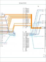
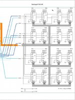
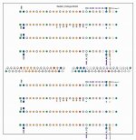
Took the spec from BOMARC's IIsi (target machine) schematic:

pin 21 - /WE -  RAMRW is tied together across the four SIMMs in Bank B. I ASSuME such is the case across the Mac II/Quadra lineup?

Bankage-L-00.jpg

Bakage-M-00.jpg

Bankage-R-00.jpg

I forget where I got the schematic for the 72 pin SIMM.

Any help with the schematic would be most welcome:

Currently the plan is to use a pair of single banked 32MB SIMMs from trag's hoard to spread 64MB across the 30 pins on the IIsi's floor. Are you saying I'll need to us one single banked 64MB 72 pin SIMM to get it to work or will a pair of 23MB SIMMs do the trick?


Gorgonops

Moderator
Staff member
Here's an important thing to think about: a "classic" 30 pin-to-72-pin SIMMsaver is taking 4 8-bit devices and paralleling them up to make them appear as a 32 bit wide device.
You know, just for the heck of it I was doing some research, and I think the distinct possibility exists that I'm wrong about the need to use all 32 bits of a standard 72 pin SIMM in parallel.

I ran across a few things you might be interested in. First off: an adapter to use a 16MB 72 SIMM in an old sound card that has 8-bit wide memory banks:

https://www.vogons.org/viewtopic.php?f=46&amp;t=41220&amp;p=393886#p393886

And here, via Google Translate, another project to use a 72 pin SIMM to max out a Soundblaster AWE32, which has 16 bit wide RAM and uses two 30 pin SIMMs. This got me headscratching about how they pulled this off without wasting some of the RAM... and I *think* I get it now. Here's a link to a volume of old Micron datasheets; it includes sheets for both individual RAM ICs and assembled SIMM/DIMM modules. Long story short, if I'm interpreting the "theory of operations" correctly 72 pin modules have four separate CAS lines on them (which you would probably normally have tied together on the computer's side), and for a write to take you have to strobe the CAS line at the right part of the cycle. So, if I'm getting that correctly, it *is* possible to use a 72 pin SIMM as if it were four 8-bit banks of RAM, each 1/4 the capacity of the whole module. (Or split it into 2 16 bit banks, etc.) If that's actually the case I suppose I stand corrected on an earlier thread stating that the inability to do so is why you don't see Apple IIgs RAM cards made out of a single 72 pin SIMMs.

The only thing I'm wondering is if it's really as easy as splitting the CAS signals from the original 30 pin banks up across the CAS lines on the SIMM or there's more to it than that. The pictures of the adapter for the GuS sound card make it look that easy, while the adapter for the Soundblaster suggests some massaging of the signals is necessary. Someone smarter than me needs to look at that Russian page.
 

Are you saying I'll need to us one single banked 64MB 72 pin SIMM to get it to work or will a pair of 32MB SIMMs do the trick?
For this to work you'll have to have some external circuitry that tracks the RAS/CAS lines and does an "even/odd" thing to select one SIMM or the other for each half the address space. It should be relatively trivial but I'm not the one to ask. (It might also have implications for RAM refresh.) Presumably a single-bank 64MB would "naturally" look like 4 16MB 30 pin SIMMs without that.


Trash80toHP_Mini

NIGHT STALKER
I've got so many SIMM savers with 4 or 8 30pin SIMMs on board and a couple of adapters to put a pair of 72pin SIMMS into a single slot that it's a bit dizzying. :blink:

I found one you'll really like! Check out this guy's work: http://randomvariations.com/author/christopher/

IMG_9017_8MB.jpg.d0a475c4372c327cd733c8c387a62a57.jpg


It's a good read, looks like he's turned a 32bit SIMM into a double banked 16bit module for a IIgs slot?

Maybe just stacking (multiplexing?) the RAM to high and low for a single 16bit bank?

Dunno how to describe it? Don't grok real schematics like this, but the project sho'nuf looks cool as hell. [:)]

gsram-72pin-v1.png.21b9c88f7b633ff052401f9b74561e24.png


His setup seems overly complicated as compared to what I'm seeing. What he sees as complexity reduction of the multiplexed four RAS/CAS line setup for translation into 16bit fans out very neatly to a four 30pin SIMM Bank in a Mac. That's why adapters were possible with no active components on them at all. Reversing that funnel looks straightforward  .  .  .  to me anyway?

I'm trying to rebuild what I did in the original, now long lost thread.  :p What's the story with those anyway? Is it a specific time frame that didn't make the translation into the new forums database or what?

 
Last edited by a moderator:

Gorgonops

Moderator
Staff member
Haven't had my coffee yet, but it looks to me like the TL;DR of most of the extra circuitry on the IIgs card is to deal with the fact that the IIgs doesn't support a RAM refresh cycle suitable for 4mbit DRAMs. (And there's also some bank decoding goo, since 8MB SIMMs are dual rank.)

https://gglabs.us/node/1935


Trash80toHP_Mini

NIGHT STALKER
Pretty neat stuff, what I can understand of it from the little I know of the Apple II architecture.

I was thinking that his using a 32bit 72pin SIMM in 16bit mode might settle any question about chunking 72pin SIMMs down to lesser bits in the backflow SIMMsaver gambit?


Gorgonops

Moderator
Staff member
I was thinking that his using a 32bit 72pin SIMM in 16bit mode might settle any question about chunking 72pin SIMMs down to lesser bits in the backflow SIMMsaver gambit?
Those other projects I linked to already proved you can treat a 72 pin SIMM as 4 8-bit chunks. (Or two 16 bit chunks, obviously, although for the record the IIgs has an 8 bit memory bus; it's "16 bit" in the same sense IBM's 8088-based 5150 PC is.) At this point I think the only question is whether you can *literally* just tie all the lines from a bank of four 30 pin sockets each to an 8-bit subset of the pins on the 72 pin SIMM and you'll be good to go, or if you'll need some logic to massage things. My gut feeling is that the answer in the case of a single-rank SIMM is "probably", but a dual-rank SIMM will need some bank select goo. (Which means for your project to use 72 pin SIMMs to fill a bank of four 30 pin sockets with 64MB of RAM might not need any logic if you use a single-rank 64MB SIMM, but you'll need some glue to use two 32pin SIMMs.)
 

couple of adapters to put a pair of 72pin SIMMS into a single slot
Unless those adapters have logic on them I'm going to hazard a guess they only work with single-rank SIMMs. (IE, it could be used to convert two 16MB SIMMs into a 32MB, but not two 32's into a 64.)


Trash80toHP_Mini

NIGHT STALKER
THX, Eudi! One single banked 64MB SIMM it is then for my prototype. Now to get PowerPCB up and running  .  .  .  misplaced the dang manual. :blink:


Trash80toHP_Mini

NIGHT STALKER
Unless those adapters have logic on them I'm going to hazard a guess they only work with single-rank SIMMs. (IE, it could be used to convert two 16MB SIMMs into a 32MB, but not two 32's into a 64.)


Nope, no logic. So I can use one to try a pair of trag's 32s in my protoboard to see if I really need any active components?


Trash80toHP_Mini

NIGHT STALKER
whoopsie, the 72-&gt;72 adapter for 2:1 has what look like the standard buffering setup for address lines, but that's it.

The adapter for four 72pin SIMMs to a single slot has active components on board.

Meanwhile I need to revive the old or start anew with the single 64MB SIMM design. I've added a funnel back out to a standard SIMM slot bank for test purposes. Gotta make sure the dingus is getting all the signals to the 72pin SIMM by installing a standard 30 pin bank downside for baseline testing the interface.

Alpha-500-PDF1.jpg

Top four rows connect to the de-socketed mobo with Pi shield hardware and the bottom rows are the test sockets. That puts the 10x10cm bo9ard up above the level of the battery holder in the sacrificial IIsi. If they don't work, something besides the reverse funnel is hinky.

 
Top