• Updated 2023-07-12: Hello, Guest! Welcome back, and be sure to check out this follow-up post about our outage a week or so ago.

3D-printed 040 PGA puller refinement

jessenator

Well-known member
Decided to pull this out of the 3D printed objects thread so I can briefly log the refining process and not further clutter the former.
One larger point of improvement: for sure is the threaded portion in the 'puller' piece: I had to insert the 'threads' piece by wrapping it with some padding and using pliers to get it seated. This might be the nature of the print support quality. Also I should note: I got the bolt piece in while off of the CPU. The pictures imply one could just thread it in by hand... I would definitely do this OFF the CPU.
I was not paying attention to grammar... "one point for improvement" might've been better...anyway, it was supposed to be an admission of incompleteness. And while I did sort out where the issue is coming from (mis-scaling on the puller threads) I did manage to create a proper one. One should be able to slip the puller on and then thread the bolt on without any issues.

One thing I have noticed, however, is that it still does tend to extricate one half of the CPU's pins first. While I was a bit cavalier in saying there wasn't any harm in it, it's probably not the best in the long term.

My next point of improvement will be fine tuning the threads. I'm printing out some test bits now to see how much finer I can make them so there's a more even lift. I suspect the current size causes a bit of a shimmy as the thread pitch is pretty tall. With the original metal version, they could simply select a fine pitch right off the shelf and there wouldn't be any issues of uneven upward lift.

If adjusting the thread pitch isn't enough, I may have to resort to widening the puller's depth(?) to cover a larger portion of the ceramic's surface area. I wonder, too if I can make the top section of it slightly thinner. I think this could have two advantages:
  1. it would permit a slight flex, allowing it to actually slip over the edge of the ceramic
  2. and when it's pulled up, and from the center, it might keep the puller from slipping out: instead pinching it
    • The bolt piece could be very gently tightened to further lend to this pinching action
I foresee this would lead to a tradeoff in durability, especially as the PLA begins to absorb moisture from the air (becoming more brittle as it does).
 

jessenator

Well-known member
Both 60% and 50% of the default threads' height works swimmingly. I'm doing one more test with the threads—widening the diameter a bit—and then I'll print a formal round 2.

I say height, because I can't be bothered to think of it in engineering terms: pitch.
 

MrFahrenheit

Well-known member
Does there come a point within a reasonable of processor insertions and removals that the socket becomes less firm on its grip of the CPU pins? In other words, would most people swapping a 68040 CPU as many as 20 times wear out the socket grip enough to cause the CPU to easily come out ?
 

jessenator

Well-known member
No idea. I'm sure there's some threshold there, but I don't know what it is. It's not like the PGA sockets are sprung, like a DIP socket header
 

jessenator

Well-known member
I'll print a formal round 2.
Well, this was a bust :ROFLMAO:

The threaded portions on their own work perfectly. Nice and snug, in fact it's pleasantly snug compared to the last print I did. However, under load, it will skip and eventually strip the threads. And the failure point is on the puller. There are enough threads on it, but it's just the material thickness to blame.

for size comparison, the working thread size is on the left, this latest revision on the right (68040 for scale)
265ZZmq.png


So I could try something in between these two, I suppose... the failure point was most likely the vertical scaling of the threads. There just isn't enough material at that scale, with a layer height of 0.2mm it's too fine. Believe me, I've tried a smaller nozzle (and smaller layer height) but it didn't end well...
 

jessenator

Well-known member
We'll see how this fares...
And it fared kind of badly. It's no better than the original. In fact it's kind of worse.
FL6ZkYil.jpg

The blue shows where it lifted first and then because there was less static friction on the pins it just kept lifting… I've been doing this on my bogus/non-chiming 040, just in case. But yeah, no matter the orientation, it would still lift on one side.

I'm still positive that has everything to do with the thread pitch being so coarse, but as we saw with the scaled height, too thin and there's no strength. I suppose I could meet somewhere in the middle and/or continue with the larger diameter to see if that makes a difference.

I've also thought of creating a matching threaded piece with a smaller tolerance. The STLs I used as a base thread pattern, positive/negative pieces, have quite a bit of tolerance/play, so it might be worthwhile to set up my own.

I could also just print a plain cylinder and filled block and then tap & die it : P I'm sure that will end well…
 

jessenator

Well-known member
Well 5th time's the charm, I guess : P

Looked back at my angle print tests and found the optimal for smaller overhangs/threads and I think this one is a decent winner!
Here's a thread comparison to working rev1:
UKQ21LKl.jpg


The wingnut part was a little bit of a struggle to start, but after that it threads well. It also pulls a lot more cleanly. As always, keep an eye on it. This one just needed a tiny bump at the end.

Also, it works with the original "Tower" or bridge piece, as they're nearly the same diameter.
 

jessenator

Well-known member
I forgot I made this thread 🤦‍♂️ I'll redirect the convo here then...

_Consider using a Leadscrew for this type of application.
Interesting! I'd never even heard of that kind of threading. I think I mentioned this in the 3D Printing projects thread, but I did adapt the basic thread geometry from a Thingiverse project: https://www.thingiverse.com/thing:193647 and modified it to suit my needs. I'm also not—strictly speaking—using an engineer's 3D program. I'm using the one I have the most experience with, since it's all free-time project development.—I've made good-looking sorts of models strictly for rendering images (old old job), but they're not printable, so it's something I'll have to spend time concentrating on to get it right.

It looks like a bolt, but if I tried to slice this for printing it would be a nightmare of extraneous geometry that would definitely cause errors:
YuYkvzB.png


_Tap and die set
I'd definitely have to do some testing, and adjust the printing specs for the 'bolt' bits. Cutting into the infill is definitely not going to work, so I'd have to increase the wall layer count.

Here's the standard count for prints I do:
XewS803.png


And here's double that, which might work:
9OTbvBj.png


There's the possibility that it would just tear itself apart :LOL: but if you never try... My knee jerk is that, though: just tearing itself apart even with a very sharp die. FDM (fused deposited material) printing doesn't really make a billet like the kind of material to mill. We used to mill plastic and/or wax billets in my tech class in high school (WA schools got a huge grant from Bill Gates I think, and they made a very cool tech lab which included a very basic CNC mill).
 

jessenator

Well-known member
Moving this here instead of inside the trading post thread
think this would work on a Radius Rocket?

No idea. There are a lot of factors and at-a-glance things I see:

Is the socket (is it even socketed?) the same height as the Quadra/Centris machines?
What's the clearance of the clock oscillator to the CPU?
Will the SMD components interfere with the placement of the tower/table piece from sitting level?

Without something in-hand to really design around, it's going to be shooting in the dark, really.
 

Nathan_A

Well-known member
It's definitely socketed, it's just a very weird socket that makes it very difficult to extract a CPU by anything but the most patient & delicate means. Lemme take a couple photos and some rough measurements.
 

Trash80toHP_Mini

NIGHT STALKER
Rocket's a PITA to do with a screwdriver. Pulled its 68040/33 with heatsink to use in the Q605 and broke one of the boxy little orange caps(?) in the process.

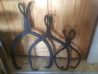
Now you've got me wondering about doing an interleaved base/puller riff on iceman's claw tongs that would slip straight down onto the 040.

Iceman-tong-puller.JPG

PCB component Interfering claw/base sections could be excised as needed for any special case like the rocket. It wouldn't require an 040 footprint+ clearance next to the CPU to slide it under from the side.

/Rube_Goldberg_mode
 

jessenator

Well-known member
Alright, I've updated the TP thread, but I wanted to just update here in more detail.

I will say I had to exert quite a lot of force to break these first-production rod/post/bolt/thingies in a tensile test, but all the same, I wanted to get it corrected.

In my test prints, no combination of wall count, infill pattern and fill percentage was strong enough—just kept breaking at around the same point as the original. I think for a piece of this size, the only option was to go full 100% infill. It wasn't that much more in terms of print time and the difference in total material use is ~1g, which in my view is negligible.

In larger-scale prints an infill pattern at <50% is usually adequate. Here's 30%
6bxAU79h.png


And 100% just 90* alternating fill layers
15PqTtn.png
 
Top