• Hello Guest! We're hosting a challenge to welcome vintage Intel macs to the MLA during the month of July! See this thread for more information.
  • We've made some quality of life improvements to the Trading Post. More info here.

Running a Mac Plus logic board on an SE analog board/PSU — anyone done this?

I'm looking at running a Macintosh Plus logic board off a Macintosh SE's analog board, CRT, and PSU, instead of the Plus's own analog board. I've cross-referenced and mapped the power and video pins between the two harness connectors.

What I want to understand is the Plus's output video signal versus what the SE analog board expects on its input — how (if at all) they differ, and whether there's anything I'd need to do to match the two up. Has anyone gone through this specific combination before, or knows enough about both boards' video/sync characteristics to weigh in?

I'm comfortable building whatever circuit is needed, so any insight into the signal differences (or confirmation that there aren't any) would be a big help.

I see some adapters out there but it's unclear if I can utilize the SE's video circuit with the Plus's logic board.

Thanks! litriSE
 
Update: got it working (mostly)!

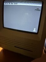
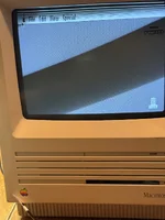
Connected a known-good Macintosh Plus logic board (1MB RAM, booting off BlueSCSI) to a known-good Macintosh SE analog board, PSU, and CRT, with power and video pins cross-referenced and wired. Direct connection, video out from the Plus straight into the SE's video in — and it boots to a fully legible System 6.0.8 desktop. Menus, trash icon, cursor all render correctly, correct aspect ratio. So the core premise works: the Plus logic board can drive the SE analog board.

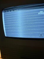
One remaining issue: there are persistent horizontal lines running across the top portion of the screen, like unblanked retrace sweep. I also tried inverting the Plus's video signal through a 74LS14 before feeding it to the SE — that made the lines worse (second image), so I don't think inversion is needed here (makes sense, since horizontal/video circuits are supposedly near-identical between Plus and SE).

Current theory: the Plus and SE use different vertical deflection circuits — the Plus has a discrete op-amp/transistor vertical sawtooth generator, while the SE (and later compact Macs) use a TDA1170 IC for vertical deflection. My guess is the Plus's VSYNC pulse width/timing doesn't quite match what the TDA1170 expects for its blanking/retrace window, even though the overall vertical frequency (60.15Hz) is correct.

Has anyone run into this specific symptom before, or knows the TDA1170's expected VSYNC pulse characteristics well enough to compare against the Plus's actual output? Photos of the result attached. Let me know if you have solved this problem. Getting close!
 

Attachments

  • image1 (1).jpeg
    image1 (1).jpeg
    887.9 KB · Views: 22
  • image0 (1).jpeg
    image0 (1).jpeg
    1.3 MB · Views: 20
Update: found the actual mismatch, working on a fix.

Scoped VSYNC directly at the connector on both boards for a real apples-to-apples (pun intended) comparison:

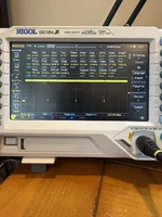
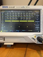
- Macintosh Plus logic board VSYNC low (retrace) pulse: ~900µs
- Macintosh SE's own logic board VSYNC low (retrace) pulse: ~200µs

So the Plus holds VSYNC low about 4.5x longer than what the SE's analog board (TDA1170-based vertical deflection) is normally fed. That lines up well with the lines appearing specifically at the top of the frame — looks like the SE's vertical circuit is getting held in what it thinks is an abnormally long retrace/reset condition.

Plan: building a 74HC123 monostable one-shot to reshape the Plus's VSYNC pulse down to ~200µs before it reaches the SE analog board, triggered on the same falling edge, output taken from the active-low Q output. Adding a small series resistor ahead of the trigger input too, since the Plus's VSYNC showed a real negative undershoot (~-1.76V) on the scope that's worth protecting against. Breadboarding it now before committing to anything permanent.

Will report back once it's built and tested on the actual hardware. If anyone's run into this specific 900µs vs 200µs vertical sync width difference between these board generations before, or has thoughts on the approach, would love to hear it.

litriSE
 

Attachments

  • SE-VSYNC-SCRN.webp
    SE-VSYNC-SCRN.webp
    113 KB · Views: 12
  • SE-VSYNC.webp
    SE-VSYNC.webp
    89.3 KB · Views: 6
  • PLUS-VSYNC_SCRN.webp
    PLUS-VSYNC_SCRN.webp
    121.9 KB · Views: 7
  • PLUS-VSYNC.webp
    PLUS-VSYNC.webp
    89.2 KB · Views: 8
Update: it's fully working. Full writeup below with final measured values, in case it's useful to anyone else attempting this.

Background: running a Macintosh Plus logic board (1MB RAM, booting off BlueSCSI) off a Macintosh SE's analog board, PSU, and CRT, in place of the Plus's own analog board.

What worked immediately: Video and HSYNC connected directly, no inversion, no extra circuitry.

The problem: with VSYNC also connected directly, the picture was otherwise correct (right proportions, legible text) but showed persistent horizontal lines across the top of the frame — looked like unblanked vertical retrace.

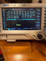
Diagnosis: scoped VSYNC directly at the connector on both a known-good SE logic board and the Plus logic board, same test point, for a real comparison. Results:
- Plus VSYNC low (retrace) pulse width: ~900µs
- SE's own native VSYNC low pulse width: ~200µs

So the Plus holds VSYNC low about 4.5x longer than what the SE's analog board (TDA1170-based vertical deflection) is normally fed. Makes sense given the SE and later compacts use the TDA1170 IC for vertical deflection, while the Plus/128K/512K use a completely different, older discrete op-amp/transistor vertical circuit — horizontal/video timing is apparently very close to identical across the family, but vertical isn't.

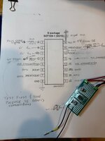
Fix: built a 74HC123 dual retriggerable monostable multivibrator to reshape the Plus's VSYNC pulse down to ~200µs before it reaches the SE analog board. Final circuit and measured values below (photo of the schematic/board attached). Built on the SO16 (D-package) variant, hand-soldered to a SOP16 breakout — pinout is identical to the standard DIP-16.

74HC123 wiring:
- Pin 1 (1A): Plus VSYNC input, through a 1kΩ series resistor (the Plus's VSYNC showed real negative undershoot on the scope, down to about -2 to -3V — this resistor protects the chip's input clamp diodes)
- Pin 2 (1B): tied to +5V (enables falling-edge triggering via pin 1)
- Pin 3 (1RD): tied to +5V (holds channel out of reset)
- Pin 4 (1Q̄, active-low output): shaped VSYNC output, feeding the SE's VSYNC input through a current-limiting pot, final measured value 3.533kΩ
- Pin 8: GND
- Pin 13 (1Q, active-high): no connection — this is the inverted-sense complement of pin 4, not needed here
- Pin 14 (1CEXT): one leg of a 10nF ceramic cap, other leg to pin 15 (no ground on this pin — followed TI's application-note wiring rather than the alternate "ground the Cext pin" convention some other manufacturers show; worked correctly as-is)
- Pin 15 (1REXT/CEXT): other leg of that same 10nF cap, plus the timing resistor network to +5V — 10kΩ fixed resistor in series with a multi-turn pot, final measured total 46.76kΩ (10kΩ fixed + 36.76kΩ pot)
- Pin 16 (VCC): +5V with a 0.1µF bypass cap close to the chip
- Channel 2 (unused): pins 6, 7, 9, 10, 11 grounded; pins 5, 12 left unconnected

Current-limiting on the output (pin 4 → SE VSYNC) was necessary because the TDA1170's sync input is spec'd for roughly 500µA and the 74HC123's output is a much stronger driver. Tested 20kΩ and 10kΩ first — both resulted in a static bright horizontal line (not enough current for the TDA1170 to lock onto sync, so vertical deflection wasn't sweeping). Final working value: 3.533kΩ.

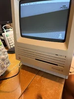
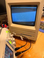
Result: fully legible System 6.0.8 desktop, correct proportions, no artifacts, stable over extended run time. Photos attached, including the scope traces showing the shaped 200µs pulse and the finished board.

litriSE

 

Attachments

  • IMG_0013.jpeg
    IMG_0013.jpeg
    2.4 MB · Views: 2
  • IMG_0011.jpeg
    IMG_0011.jpeg
    1.2 MB · Views: 4
  • IMG_0016.jpeg
    IMG_0016.jpeg
    1.7 MB · Views: 5
How strange. I wouldn't have expected that much difference in the VSync signal considering both machines have the same refresh rate.

Nice work.

Can the reverse be done too?! A Plus in an SE? :)
 
This is what happens if you hook up a Classic II board to an SE analog board. Looks like just an inverter is needed?

View attachment 101988
Hum, looks like the signal might be a little too hot as well. I think I remember someone doing a project to change this? Or they made a product for video capture compatible with both or something. Anyway, I've seen a similar picture before is kind of what I mean!

Weird they inverted the signal. Guess it saved a chip or something.

Edit - actually, if the vertical return is inverted, of course it shows. Doesn't mean it is too strong, just it isn't set to black, so it paints on the screen
 
How strange. I wouldn't have expected that much difference in the VSync signal considering both machines have the same refresh rate.

Nice work.

Can the reverse be done too?! A Plus in an SE? :)
Thanks! Yes, that surprised me too at first. The refresh rate (frequency) and the pulse width (duty cycle) are actually independent parameters — both boards can agree perfectly on 60.15Hz overall while disagreeing wildly on how long VSYNC sits low within each of those cycles. In this case the Plus's discrete op-amp/transistor vertical circuit apparently just holds the reset condition open a lot longer than the SE's TDA1170 IC needs.

On the reverse (SE logic board → Plus analog board) — good question, and honestly I don't know. My guess is it's the same problem in the opposite direction: the SE's ~200µs pulse would probably be too short for the Plus's discrete circuit to fully discharge/reset before the next sweep starts, rather than too long. That could mean incomplete retrace instead of unblanked retrace — a different-looking artifact, maybe at the bottom of the frame instead of the top, or some kind of vertical compression. But that's a guess, not something I've measured. Same approach would apply: scope the Plus analog board's actual sync requirement directly rather than assume, then build whatever shaping circuit the numbers call for — in this direction probably a pulse *stretcher* rather than the shrinker I built here. Since a 74HC123's output width only depends on its own REXT/CEXT values (not on the input pulse width), the same circuit topology should work for stretching instead of shrinking — just retune the timing components for ~900µs instead of ~200µs. Bumping CEXT up (say to 22nF instead of 10nF) keeps REXT in a more reasonable range too, roughly ~91kΩ instead of needing a ~200kΩ pot. Everything else about the circuit — trigger setup, current-limiting output stage — would need its own measurements against the Plus analog board specifically before building it, same as the original.
 
This is what happens if you hook up a Classic II board to an SE analog board. Looks like just an inverter is needed?

View attachment 101988

Looks like two separate issues here, not one.

The inverted polarity (black/white swapped, everything else geometrically correct) is a video signal issue — try an inverter in the video line: 74HC04/74HC14, or 74LS04/74LS14 if you want to stay closer to period-correct TTL levels (lower output swing, a bit more forgiving on an improvised bench setup).

But I also see the same horizontal lines near the top of the frame that showed up in our Plus→SE swap earlier in this thread — that turned out to be a VSYNC pulse-width mismatch (Plus held VSYNC low ~900µs, SE's own board expects ~200µs). Worth scoping VSYNC on a known-good SE logic board vs. the Classic II board, same test point, to check if there's a similar mismatch. If so, the 74HC123 monostable approach from earlier in this thread should work here too, just retuned to whatever number you measure.
 
But I also see the same horizontal lines near the top of the frame that showed up in our Plus→SE swap earlier in this thread — that turned out to be a VSYNC pulse-width mismatch (Plus held VSYNC low ~900µs, SE's own board expects ~200µs). Worth scoping VSYNC on a known-good SE logic board vs. the Classic II board, same test point, to check if there's a similar mismatch. If so, the 74HC123 monostable approach from earlier in this thread should work here too, just retuned to whatever number you measure.
I thought that but I think the second issue is an artifact if the first. The horizontal lines are the gun flicking from bottom to top of the screen. Usually the intensity is "black" so it doesn't add anything to the phosphor brightness, but here, because the signal is inverted, it is "white" so it draws up the screen and is visible.
 
I thought that but I think the second issue is an artifact if the first. The horizontal lines are the gun flicking from bottom to top of the screen. Usually the intensity is "black" so it doesn't add anything to the phosphor brightness, but here, because the signal is inverted, it is "white" so it draws up the screen and is visible.
That's a really plausible explanation, and simpler than what I was suggesting — if blanking during retrace is just achieved by the video data sitting at "black" level rather than a dedicated blanking signal, inverting the whole video line would flip that blanked period to "white" and make the retrace sweep visible on its own, no sync timing issue required.

Worth noting it's a bit different from what we found in the Plus→SE case earlier in this thread though — there, video was never inverted, and the lines were still present with correct polarity; they only cleared up once we corrected the VSYNC pulse width itself. So similar-looking symptom, likely a different root cause here vs. there.

Given that, probably the right move is sequential: fix the video inversion first (w/ 74HC04/14 or 74LS04/14) and see if the lines disappear as a side effect, like you're describing. If they're still there after that, then it's worth scoping VSYNC pulse width the same way we did for the Plus, since that would rule your theory out and point back to a timing mismatch instead.
 
Back
Top