• Hello MLAers! We've re-enabled auto-approval for accounts. If you are still waiting on account approval, please check this thread for more information.

LC475 DynaComp PSU fireworks!

Hello!

I recently picked up a clean-looking LC475. Gave it a visual once-over, no caps looked bad on the board or the PSU (a DynaComp DCF353, 240V 'cos it's a UK machine).

Checked the PSU output rails and it all looked fine.

Started it up and again, fine, but very noisy audio. Then occasionally on-boot it'd get stuck making a 'thudthudthud' sound from the speaker, with the fan failing to spin up fully. Checked the rails again and they were bouncing up and down.

So at this point, I'm thinking: recap the logic board to fix the messy audio, and recap the PSU to fix the occasional startup failures.

I recapped the logic board with the recommended surface-mount tantalums, and it started perfectly fine and with clean audio.

But then my luck ran out.

On a second power-up it did the 'thudthudthud' thing... and then... a red glow and magic smoke appeared around CR10 on the low side of the PSU, and then -- rather spectacularly -- C136 on the logic board turned into an indoor firework. Yanked the power immediately, of course.

First plan is to see if I can resuscitate the PSU. I've removed all electrolytics from the board (along with the tell-tale fishy smell, although actual crusties were minimal). The diode at CR10 is indeed open-circuit in both directions.

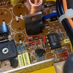
So, wondering if anyone can help identify what part CR10 is? It's right next to the L7905CV regulator, so I'll check that for shorts too. Attached is a photo of the failed CR10.

Once I've got the PSU outputting nice voltages, I'll replace CR136 on the board and cross my fingers. I've checked dozens of times that I got its polarity correct (I have... according to the silkscreen at least! I wonder if there's an error?)

Any advice appreciated!

Cheers,
Chris
 

Attachments

  • psu-dynacomp-dcf353-cr10.jpg
    psu-dynacomp-dcf353-cr10.jpg
    293.3 KB · Views: 35
Here’s what likely happened:

C136 is on a +5V rail:

IMG_4827.jpeg

I’m guessing you used a 100uF, 6.3V part for C136, as specified by Recap-a-Mac, since this is the go-to reference and you say you used the recommended values:

IMG_4828.jpeg

While 6.3V is fine on a 5V rail is fine if you’re replacing with electrolytics, it's absolutely not for tantalums. The latter need 'derating', i.e. specifying 2x headroom, otherwise they are prone to fail in the way you have seen.

So for a 5V rail, 10V caps are recommended; on a 12V rail, 25V caps.

Your PSU has an unstable +5V rail and this is the other factor here. It probably peaked too high for C136 to handle, whereas the original caps, being electrolytics, could take it.

Ah, that makes sense! I shall stock up on 10V and 25V replacements and redo the recap!

Still wondering about what part that C10 diode on the PSU is -- I'll desolder it and see if I can make out any of the markings. If I can figure out a suitable replacement for that, I'll recap the PSU and test it thoroughly before re-fitting it to the machine (I have a couple of power resistors suitable as a safe load for running PSUs outside of computers.)

(edit to add: I hope the 5V spike didn't kill anything else on the board... I did have an immediate feel-around after pulling the plug to check for hot ICs and all felt ok... but... well, fingers crossed it survived!)
 
Still wondering about what part that C10 diode on the PSU is -- I'll desolder it and see if I can make out any of the markings. If I can figure out a suitable replacement for that, I'll recap the PSU and test it thoroughly before re-fitting it to the machine (I have a couple of power resistors suitable as a safe load for running PSUs outside of computers.)

When I recapped my Dyna Comp, I had to pull a bunch of components and clean them because they were coated in corrosion from the nearby capacitor leakage, and I wrote down info about them here: https://68kmla.org/bb/index.php?thr...p-dcf-353-power-supply-woes.35646/post-550942

Luckily, it looks like CR10 was one of the ones I removed and cleaned. It was a 1N5231B, which appears to be a 5.1V Zener diode. I'm in a 120V area but I'm assuming it's the same either way.
 
I hated the LC power supplies, and decided to replace the innards of those things with MeanWell psu. lower ripple, cleaner and more power overall. No brainer for me…. Less time lost and 100% success rate. And it looks identical from outside anyway
 
I hated the LC power supplies, and decided to replace the innards of those things with MeanWell psu. lower ripple, cleaner and more power overall. No brainer for me…. Less time lost and 100% success rate. And it looks identical from outside anyway

That's a good point. I do want to bring up one caveat with that approach, not relevant to this particular thread but something to keep in mind if anyone stumbles upon this discussion in the future. If you do the aftermarket PSU approach with the LC III, definitely make sure that you install C22 on the LC III's logic board backwards from what the silkscreen says, especially if it's a tantalum.

The reason I bring that up here is in both cases I'm aware of where a tantalum C22 blew up (because it was installed following the incorrect silkscreen), it happened with an aftermarket power supply. My theory is that the aftermarket supplies are capable of supplying more current on the -5V rail, which leads to disaster with a reversed tantalum. With the stock power supply it causes the -5V rail to only be like -2.5V, but it doesn't seem to explode.

I think this also explains why Recap-a-Mac hasn't ever run into any crazy issues with the LC III and seemed annoyed about it when my post about it took off last year. I think if he had ever tried an aftermarket PSU he would be singing a different tune. FWIW, I love his site, it's a great reference -- although I agree I wish he would recommend de-rating tantalums.
 
FWIW, I've had C136 explode on a couple boards (not sure if it's the same component number on the other LCs, but the equivalent cap anyway) now when fitted with tantalum caps. It's driving me away from them too.
 
Thanks for the info, all! I’ll keep the de-rating requirement in mind for — maybe will stick with new electrolytics on a future restoration.

@pizzigri — just out of curiosity, what MeanWell did you use to replace the LC PSU’s innards? Probably won’t go that route this time, but I’ve used MW PSUs in a few other machines (they fit perfectly in Atari MegaSTEs!) with great results.
 
Thanks! Might grab one even if I don't use it in the LC475's PSU since I'm sure I'll find a use for it.

Just as a note, I got one that had a dead -5 line from the factory; so if you get one to use later, it's probably a good idea to check all the rails are working before you put it away.
 
This is an odd one because I have a 475 and used a tantalum 6.3V cap there and I also have a re-capped DynaComp PSU and I've never had any issues.
 
This is an odd one because I have a 475 and used a tantalum 6.3V cap there and I also have a re-capped DynaComp PSU and I've never had any issues.
I think it’s fine because you’ve got a stable PSU. It’s just the explosive way that tantalums fail if things go wrong that makes it a good idea to derate them. But then… I don’t think Apple did this back in the early nineties on the Quadra 650/700/800 boards… so I don’t know.
 
Back
Top