• Hello MLAers! We've re-enabled auto-approval for accounts. If you are still waiting on account approval, please check this thread for more information.

Mystic Color Classic VGA Mod Rev D Analog Board Black Bars

mcbeav

6502
IMG_3542.jpeg

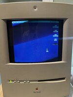
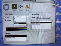
I can't seem to get rid of the black bars. I followed the guide from https://powercc.org/640x480/ I have a revision D analog board, but the step that is different (that is listed) is to isolate pin 20 by cutting since the jumper J28 does not exist. The resolution is properly set to 640x480 but I can not adjust the black bars out. There is not much info on the revision D board out there that I have found. Everything seems to be for revision C. I did check that I properly isolated the required pins with a multimeter, and soldered the wires in the correct positions. I'm not sure what the issue is and where to go from here. Does anyone have any input?
 
It looks like your pincushion settings are out of whack. Did you try adjusting the horizontal bow potentiometer(pb)
 
It looks like your pincushion settings are out of whack. Did you try adjusting the horizontal bow potentiometer(pb)
Yeah, I tried, i can asjust it so its not so severe, but the black bars are even wider. I just left it like that out of frustration. in general it's acting like the horizontal deflection voltage mod portion didn't work at all. I can confirm I did test that there was a break when making the cut and the did test that the wire is properly soldered.
 
It looks like your pincushion settings are out of whack. Did you try adjusting the horizontal bow potentiometer(pb)

this seems to be about the best I can adjust it. The geometry isn't great, which I can live with, but the black bars are bothersome. It seems like the horizontal deflection voltage change didnt take looking at how thick the black bars are. Any wider and the PB is blown out and the image is warped as shown in the first image in the original post. It would seem the sense line change did take seeing as It is at 640x480 resolution. I'm really not sure where to go from here. I guess I could try soldering a jumper from pin 8 to pin 10 instead of 12, but I think that is the other side of the same component.

IMG_3544.jpeg
 
That looks a lot better!!! All we need to resolve is horizontal width at this point. I know the mod talks about adjusting the Horz deflection voltage as part of the mod. If you raise or lower the monitors b+ volltage this can cause the monitor to adjust In Size, but yur picture looks good.if your horizontal width is adjusted to its max you can 'normally' replace the polypropylene's that are part of the width circuit to widen (or shrink) the picture. The lower the capacitance the wider the picture.
I've done it on other monitors, but I haven't done it to a color classic before A little investigation is in order for me to tell you where to look. I have a lc 575 analog board I can look at. Is the color classics a lot like it?
 
Last edited:
That looks a lot better!!! All we need to resolve is horizontal width at this point. I know the mod talks about adjusting the Horz deflection voltage as part of the mod. If you raise or lower the monitors b+ volltage this can cause the monitor to adjust In Size, but yur picture looks good.if your horizontal width is adjusted to its max you can 'normally' replace the polypropylene's that are part of the width circuit to widen (or shrink) the picture. The lower the capacitance the wider the picture.
I've done it on other monitors, but I haven't done it to a color classic before A little investigation is in order for me to tell you where to look. I have a lc 575 analog board I can look at. Is the color classics a lot like it?
So i got it to work! I fixed the issue by changing the jumper from pins 7-12 to pins 7-10, which is the same component but there are different components in between, so I guess that was the fix. I used the guide found at https://www.micromac.com/instructions/CC_Video_upgrade/index.html for the information. For anyone looking at this in the future with the same board revision and problem, hopefully you can make sense of this:

I followed the guide at powercc.org. Follow the guide for the sense lines, and followe the guide for the horizontal deflection modification, however, solder pins 7 to pin 10 instead of pin 12.
 
7 to 10 is called “high-res” mod that will put voltage to 84V from original 60V. 7-12 will only put voltage to 68.4V which is considered much safer in the long term.
 
Please also check https://colourclassicfaq.com/general/vga.html. I just did the same mod last weekend without any issue. I think you might mixed the mod to the horizontal voltage (7 to 12 is vga mod) and mod to the sense lines (only isolate pin 20 is hi-res mod). I also isolated pin 25 and added wire to short pin 20 and pin 24 as part of the “vga mod”
 
Please also check https://colourclassicfaq.com/general/vga.html. I just did the same mod last weekend without any issue. I think you might mixed the mod to the horizontal voltage (7 to 12 is vga mod) and mod to the sense lines (only isolate pin 20 is hi-res mod). I also isolated pin 25 and added wire to short pin 20 and pin 24 as part of the “vga mod”

I don't believe I mixed anything up, but maybe I'm not understanding correctly. I believe I correctly modified the sense lines, otherwise I wouldn't have the options for 640x480 and 800x600. You don't need to do the horizontal deflection part of the mod to enable those resolutions, you only need to modify the sense lines. I have a revision D analog board, so I isolated pin 20 by cutting the trace, and then isolated pin 25 by cutting the traces above and below the pin, then I soldered a jumper wire from pin 20 to 24. Then onto the horizontal deflection mod I isolated pin 8? (the pin next to 7 that every guide shows needs to be isolated). Then I soldered a jumper wire from the isolated pin (pin 8?, there is no actual screen printed number for this pin but its next to 7) to pin 12, but it acted as if it did not work as shown in my first photo attached to the original post. I disassembled the machine twice to check continuity and make sure everything was properly soldered. I don't have a bench meter so I can't accurately check the resistance of the horizontal deflection jumper once its been soldered as shown in JDW's video on the subject, but i can check the continuity, and it's soldered. So what could be the issue I am having? I tried switching the jumper for the horizontal deflection to jumper pins 8-10 because I didn't know what else to do. As far as I can tell I properly performed the horizontal deflection part of the mod, but I have thick black bars as if I didn't or it's not working.
 
Please also check https://colourclassicfaq.com/general/vga.html. I just did the same mod last weekend without any issue. I think you might mixed the mod to the horizontal voltage (7 to 12 is vga mod) and mod to the sense lines (only isolate pin 20 is hi-res mod). I also isolated pin 25 and added wire to short pin 20 and pin 24 as part of the “vga mod”

I just went and changed the jumper back to 8-12 and again, thick black bars. With the 80V mod (jumper 8-10), i was able to properly adjust the screen to the full width and height with good geometry. This is the widest i can adjust the screen without blowing out the geometry. I can't make any sense of this. I don't understand why I'm getting these results. I can't find anyone else with the same issue.
 

Attachments

  • IMG_3547.jpeg
    IMG_3547.jpeg
    1.9 MB · Views: 10
Please also check https://colourclassicfaq.com/general/vga.html. I just did the same mod last weekend without any issue. I think you might mixed the mod to the horizontal voltage (7 to 12 is vga mod) and mod to the sense lines (only isolate pin 20 is hi-res mod). I also isolated pin 25 and added wire to short pin 20 and pin 24 as part of the “vga mod”

On second check maybe the sense lines are not correctly done because I have a revision D board. I did follow the instructions exactly on powercc.org, which match any other instructions that are for the "new sense lining procedure" but my resolution options are as shown in the attached photo. I'm not sure if this is correct and maybe this is causing my issue. I did see another post that someone did the same procedure as I did with a revision D board but had a different problem. They had a rolling screen issue. The poster was sailcat.

On the site you shared: https://colourclassicfaq.com/general/vga.html it shows a board without the J78/J79 connector at the bottom of the page which is the board that I have and it shows to make a cut at either side of the red arrows at pin 20 to isolate pin 20, which I have properly done and did test that there is no continuity between pin 20 and 18 or any other pin for that matter. I did properly follow these instructions so unsure of why the sense line part of the modification did not properly work as planned. Instead I ended up with different resolutions.
 

Attachments

  • IMG_3551.jpeg
    IMG_3551.jpeg
    2.6 MB · Views: 10
Last edited:
Back
Top