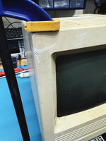
martona Posted July 3, 2012 Report Share Posted July 3, 2012 Hi, I have a very nice functioning Portable but I'm worried about the 20+ year old HDD. I'd love to replace it with a CF card, but for that I'd need one of those infamous 34-to-50 adapter cables. I don't really want to risk making my own. I'm wondering if someone here maybe has a spare one, or could make one for me? Given that I'm new here I'd gladly pay in advance. TIA! Quote Link to post Share on other sites
mcdermd Posted July 3, 2012 Report Share Posted July 3, 2012 Where are you located? Quote Link to post Share on other sites
martona Posted July 4, 2012 Author Report Share Posted July 4, 2012 USA, Southern NH and Boston for the most part, but I very frequently travel to Europe as well. Quote Link to post Share on other sites
Trash80toHP_Mini Posted July 4, 2012 Report Share Posted July 4, 2012 I posted the pinout info necessary to build this adapter cable in a previous thread about the luggable. It's very straightforward . . . . . . but a double ended, or double sided, adapter PCB for 2.5" PowerBook SCSI Drive RA socket and a 3.5" SCSI cable header would be a great community project. Quote Link to post Share on other sites
martona Posted July 4, 2012 Author Report Share Posted July 4, 2012 Thanks, I did see the pinout post but I'm not sure where I'd source the parts, and then there's the time needed... oh hell, the truth is I'm just a bit clumsy. I really wouldn't mind paying for a pre-made cable though. Quote Link to post Share on other sites
Trash80toHP_Mini Posted July 4, 2012 Report Share Posted July 4, 2012 Heh! I finally found it too! from: Lot of Goodness Have you got the SCSI interface for the CF Card already? If so what is the form factor of the adapter and the spec for the connector? If you don't have the adapter yet, get that end of it nailed down before worrying about the cable. Quote Link to post Share on other sites
martona Posted July 5, 2012 Author Report Share Posted July 5, 2012 I bought a CF ActecMonster and was planning on using that with a 4GB CF card. In case that doesn't work I have a couple of IDE-SCSI bridges, one with a standard 50-pin SCSI connector (and the usual 4-pin Molex power) the other with a UW connector but I have an adapter to convert that to the old 50-pin standard. Regardless of the drive used, it's the usual 50-pin SCSI and 4-pin Molex connectors. Quote Link to post Share on other sites
Bunsen Posted July 5, 2012 Report Share Posted July 5, 2012 With a bit of careful keyword search massaging, one can often find oddball connectors on ebay in small quantities. Quote Link to post Share on other sites
mcdermd Posted July 5, 2012 Report Share Posted July 5, 2012 I did see the pinout post but I'm not sure where I'd source the parts I made mine with a 50-pin SCSI ribbon cable, a 34-pin floppy drive ribbon cable and a razor blade. I used the SCSI connector and it's cable but only a connector from the floppy cable. I sliced up the individual wires from the ribbon and followed the pinout chart to connect them to the floppy connector. It took maybe an hour and didn't cost me anything as I already had the parts on hand. Quote Link to post Share on other sites
tmtomh Posted July 6, 2012 Report Share Posted July 6, 2012 Very clever solution! Quote Link to post Share on other sites
Trash80toHP_Mini Posted July 6, 2012 Report Share Posted July 6, 2012 tmtomh is right, this is a clever way to do this particular adaptation. I like this approach because it's a down and dirty conversion that keeps all the wires the same length. did you start with a long section of ribbon cable and twist the signal lines? The shield lines of the alternating pairs would be tied back to to common ground on the HDD's PCB. mcd, you lifted the Insulation Displacement Connector's (IDC) strain relief and lid? That's the way I've done the same thing in the past for testing. I wound up making a PCB to do two different adaptations at once for the project along with providing the mounting unit. I'd still like to see an adapter PCB done that acts as a mounting board for a 2.5" lappy HDD in the Luggable. Are you using a 3.5" HDD or a 2.5" Lappy Drive with an adapter with that cable in your luggalbe? . . . meanwhile, back at the banana ranch: Google searsh string: idc ribbon cable assembly howto http://www.thekanes.org/2010/02/07/how-to-make-a-ribbon-cable/ (PDF) IDC Cable, Headers & Connectors IDC (Insulation Displacement Connector) Ribbon Cable Happy hacking, m! Quote Link to post Share on other sites
mcdermd Posted July 6, 2012 Report Share Posted July 6, 2012 I think a picture is worth a thousand words here: Yes, I lifted the top off the IDC, pressed the wires into the pin "teeth" and replaced the top. I also forgot that I used a separate set for the Molex power connection. I made the cable but actually only used it for a few weeks with a standard, 3.5", 50-pin Apple SCSI drive. After that, I found a Conner drive to do a PCB swap with in order to have an "original" drive. But I'm a pack rat so I keep the cable around, just in case. Quote Link to post Share on other sites
Trash80toHP_Mini Posted July 7, 2012 Report Share Posted July 7, 2012 Eeeek! Bundling unshielded signal & address wires together like that is just begging for crosstalk problems on a parallel interface! It'd be much better to split the cable so as to leave the signal/ground pairs intact right up to the 34 pin connector, twisting each pair several times on the way there and then nipping the ground wire just short of the connector, if not tying them together to ground at that end. That way you can bundle the twisted pairs together without too much worry about crosstalk rearing its ugly head. Other than that one caveat, nice hack and very helpful piccie, mcd! Quote Link to post Share on other sites
mcdermd Posted July 9, 2012 Report Share Posted July 9, 2012 Hm, hadn't thought of that and I like the advice. I may be looking at making a new one just for fun, then Thanks, Trash! Quote Link to post Share on other sites
martona Posted July 9, 2012 Author Report Share Posted July 9, 2012 Thanks everyone! So I'm buying these then: http://www.amazon.com/gp/product/B007R2JL18 http://www.amazon.com/gp/product/B007R2JEV0 http://www.amazon.com/gp/product/B007R2JF9Q I apologize for my ignorance but what exactly do I do with the wires that are not meant to be connected on the 34-pin side? It appears that all odd wires on the 50-pin side are left unconnected. Do I take the odd wires and twist them around the corresponding even ones, then just leave them unconnected right before the 34-pin connector? I think I get the wiring diagram for the most part, but what happens with 11 & 16 on the 34-pin side? They are marked as GND and don't seem to not reach the 50-pin side at all. Does the 50-pin connector really not need any GNDs hooked up? Finally, this is AztecMonster specific: the manual says the MacPlus will not boot from this "drive" without cutting wire 40 (RST). Is this anything I should worry about with the Portable? Quote Link to post Share on other sites
martona Posted September 12, 2012 Author Report Share Posted September 12, 2012 I finally got around to making the cable. It's easier than I thought, but I'd need a couple of clarifications: I'm assuming the GND wires on the 34-pin side can be connected to any one of the odd wires on the 50-pin side. Is that correct? Or should they be connected to the molex GND wire? (As per the photo of the completed cable, it seems the 50-pin connector's odd wires have been used.) What about TPWR? Should I hook it up? The diagram shows pin 26 from the 50-pin side connected together with molex pin 4, and they also connect to pins 23, 24, 33, 34 on the 34-pin side. Is this the right way to do it? Or can leave TPWR disconnected on the 50-pin connector, and just connect molex pin 4 to the four pins on the 34-pin connector? I'm asking because on the photo above exactly this seems to have been done. Thanks in advance! Quote Link to post Share on other sites
Trash80toHP_Mini Posted September 12, 2012 Report Share Posted September 12, 2012 All the odd pins on the 50 Pin Connectors are tied to ground, I forgot to show that on the cleaned up version of the drawing. Other than the four schematic, sorta . . . I've shown TPWR to be tied to the Molex Connector on the cleaned up version of the drawing. Termination Power can probably be tied to the Molex Connector, but it's likely much better to connect it only to the SCSI Bus. There the 5V feed has hopefully been conditioned whereas the raw power feed at the Molex Connector certainly won't have been. On second thought, keep it isolated, better safe than sorry. Same thing for ground lines at the signal level, they had probably best be kept clean as well. Connect just pins 37-40 on the 34 pin connector to the Molex Ground Lines. Tie the rest to the SCSI Bus. Remember, I'm just an electrical plumber, not really an electron pusher . . . . . . never trust a guy who doesn't have, and know how to use, an Oscilloscope! edit: see, never trust a . . . BooBoo been crossed out, correction: Pins 27-30, as noted by martona below. Quote Link to post Share on other sites
martona Posted September 12, 2012 Author Report Share Posted September 12, 2012 Thanks for the quick response! I'll finish the cable tomorrow, and... fingers xed. I have had the Portable recapped, all that's left to do is install the 8-meg RAM expansion and replace the noisy, power-hungry HD with a CF SCSI module. I'll keep TPWR a single wire then, and based on the "unclean" drawing you just posted, it'll go to pin 34 on the Mac Portable side. All other 5V pins will go to the molex feed. Correct? I feel the need to ask because this isn't in line with the photo posted above, mcdermd seems to have used the molex connector solely for everything above pin 22, and I have to assume his 50-pin TPWR doesn't go anywhere. Regarding GND, I'll use molex for pins 27,28,29 & 30. I'm using a couple of the odd SCSI bus lines for GND pins 6 & 11 (can't remember which ones I hooked up exactly). The rest of the odd lines on the 50-pin side are cut (other than the two I singled out for GND 6 & 11), just like on the photo; I'm assuming that's fine. Quote Link to post Share on other sites
Trash80toHP_Mini Posted September 12, 2012 Report Share Posted September 12, 2012 That's what I meant . . . oops! Strip your ribbon cable into signal/ground pairs, twist them a few times before terminating just the signal/control line on the IDC connection. You can snip the alternating (signal paired) ground lines just before they hit the the IDC connector. Running the twisted signal/ground pairs will help tremendously in keeping crosstalk at bay. See above. Quote Link to post Share on other sites
martona Posted September 12, 2012 Author Report Share Posted September 12, 2012 Thanks! Yes, I saw the crosstalk mention above, but... but.. the photo... To be perfectly honest I was concerned about not finding the right wire when I get to the 34-pin connector if I twist odd & even pairs together. That's why I cut the gordian knot, so to speak. Of course I could have just used a sharpie before twisting the pairs. But such a "complicated" solution did not occur to me when I started, and It's too late now, I only need to do the DP wires and add the Molex connector. I do have material for another cable, so I might make a proper one if this one works. (If it doesn't, I'll HAVE to make another one.) Quote Link to post Share on other sites
martona Posted September 12, 2012 Author Report Share Posted September 12, 2012 Well, the cable is finished. It's not pretty, but it's mine. Now I'm off to hook it up. Hopefully there will be no smoke. Quote Link to post Share on other sites
Trash80toHP_Mini Posted September 13, 2012 Report Share Posted September 13, 2012 Easy trick.: 01) leave an extra couple of inches of ribbon sticking out the off end side of the 50 pin IDConnector 02) split all the wires on that side, lopping off the signal lines 03) the remaining lines will all be connected to the ground side of the cable, strip the ends 04) bundle them together and attach the alligator clip lead of a $.99 Continuity tester to the bundle 05) leave about an extra inch of length on the business end of the ribbon cable 06) mark across the entire width of the cable at the IDC point with a sharpie. 07) split all your pairs from the beginning to end 08) split that one inch extra on each twisted pair 09) apply continuity tester to see which of the pair doesn't light up 10) nip off the side that does light up about 1.5" short of the sharpie line with your dikes 11) strip the ground line waste off the signal line back to the nip 12) punch your signal lines down on the IDC connector's forks right at the sharpie line (for equal length signal correctness) Did I mention using a Vise to do the final punchdown of the IDC tops? Quote Link to post Share on other sites
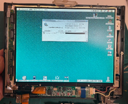
martona Posted September 13, 2012 Author Report Share Posted September 13, 2012 Thanks Trash80, that's actually pretty cool! I may have to do another cable in which case I'll follow the above steps. There was no smoke, but despite the below photos, it's not a complete success either. I had to make one modification to the diagram: TERMPWR should be disconnected. All 5V pins from the 34-connector side go to the molex red wire. The TERMPWR line on the 50-pin side is cut. This way I got the Portable to recognize the disks. (In my photo above TERMPWR is still connected to a 5V pin, I had to change this to breathe life into the system but forgot to snap a new pic.) FWIW mcdermd's photo has TERMPWR disconnected too. But I still have one problem. There may be something wrong with the cable I made, or the harddisks, or possibly the diagram, but here's the behavior I'm seeing: - With the original 34-pin HD installed, the Portable powers on and boots fine. - With the AztecMonster, the Portable powers on and after some deliberation it flashes the dreaded disk with a questionmark. At this point if I press the reset button on the machine it boots fine. (As per the photo above.) This isn't some one-off instability issue; out of 20 cold starts all of them went the same way. Have to wait for the flashing questionmark, then press reset to get it to recognize the HD. - I tried it with a regular 50-pin Apple/IBM SCSI HD (it came from my Color Classic) and I get the same behavior: power on -> questionmark -> reset -> boot, so this isn't the AztecMonster's problem. Any thoughts? Just for kicks I disconnected the RST wire temporarily, and that resulted in a no-boot scenario; the reset button stopped having an effect. Reconnecting RST reverted to the behavior described above. I'm at a loss. Quote Link to post Share on other sites
martona Posted September 14, 2012 Author Report Share Posted September 14, 2012 Well, this is interesting. I made another cable so I don't have to keep pressing Reset to boot my computer. This guy posted wiring instructions too: http://web.archive.org/web/20080705022723/http://www.antinode.org/mac/port_scsi.html They're very much in line with Trash80's diagram, except he reached the same conclusion I did: TPWR should be disconnected. Anyway, I followed the advice above re. twisting the ground wires, etc. Double and triple-checked every connection. The new cable turned out stunning. I hooked it up, and.... flashing questionmark. Press Reset: smiling Mac, boot, no problem. I found a workaround though: Setting the HD's ID to ANYTHING above 0 cures the problem. I currently have it on 1, and it cold-boots just fine. Leaving it at zero requires me to press Reset. Totally unscientific speculation: Is it at all possible that the Portable starts probing the SCSI bus way too early, and the HD is not yet read when the probe is at zero? But a few milliseconds later, the HD can be found at ID 1? Did anyone here have issues running a Portable internal HD on ID 0? In any case, thanks everyone for your help with the cable! -Marton Quote Link to post Share on other sites
Trash80toHP_Mini Posted September 15, 2012 Report Share Posted September 15, 2012 Thanks for confirming that I was mostly right, I'm no expert. Maybe I can find something in the Portable Docs about that termination power quirk. Got a pic of the new cable to share? Quote Link to post Share on other sites
Recommended Posts
Join the conversation
You can post now and register later. If you have an account, sign in now to post with your account.