• Hello MLAers! We've re-enabled auto-approval for accounts. If you are still waiting on account approval, please check this thread for more information.

Monitor "high resolution"monocrome MO400 arcing

I connected an LC 475 to a High-Resolution Monochrome Monitor MO400, specified for 640×480.

https://lowendmac.com/1989/apple-high-resolution-monochrome-monitor/

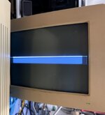
The monitor produced an image for about 5 seconds, then emitted a loud crackling noise consistent with high-frequency arcing. I immediately powered it down.


On inspection, I found no obvious damage: no burn marks, no physical cracks. The PSU rails are stable, and I verified continuity on traces, capacitors, and checked the flyback transformer for visible defects—everything appears normal but I took the opportunity to reflow the contacts.

The noise originated from the vicinity of the flyback transformer.

My working hypothesis is that the Performa 475 was driving the monitor at a resolution higher than 640×480. Without protection circuitry (just guessing here), the CRT may have attempted to sync at the higher frequency, resulting in arcing in the flyback section.

Is anyone here experienced with CRT diagnostics who can confirm or suggest further tests?
 
My working hypothesis is that the Performa 475 was driving the monitor at a resolution higher than 640×480. Without protection circuitry (just guessing here), the CRT may have attempted to sync at the higher frequency, resulting in arcing in the flyback section.
I doubt this would damage the screen. I‘ve previously connected an M1212 to improper input signals and it just showed garbage…

Are you really, really sure about the lack of solder joint cracks? You often cannot really see them…
 
Oh and the Performa 475 should usually detect the monitor type and not output bad resolutions if an Apple Display is connected.
 
1758134461703.png

1758134484195.png

Is there any chance of replacing the flyback?
Would an epoxy potting compound work to prevent the arcing?
Time to say "RIP?"
 
Is the red circled area where the arcing is taking place?

Are you certain that it's not supposed to look like that?

I don't know that there are any wires in the place you've circled; I think they're all in the cylindrical part, and the thick square-sided loop is the transformer core (inside of a plastic shroud since it's probably somewhat fragile). Unless something is very wrong, the core should carry no voltage at all, and even if it were energised, both sides of the area you circled should be at the same voltage because it's basically the same big piece of metal (so no reason for electricity to arc there).

If I'm right, then the reason it looks split there is because flyback transformers have a gapped core, and that's the gap. In other words, it's on purpose.

See also https://www.angelfire.com/oh3/ebjoew/Flyback.html (angelfire dot com! you may need to try a few times to see all the images, but this one shows where the wires might be).
 
Thanks for this.
The arc is between the flyback and the cage box around it; this is for sure. The line below is to emphasise the cage.
1758150885600.png
I checked again after your remark.
You were right, the arc originates from a hole I saw after further inspection.
1758153431776.png

Can an epoxy impede the arc? But the coil is probably damaged inside.
Is there a compatible flyback I can use?
 
You could try some high voltage putty or carona dope, but it's a band aid if it works. The hole was most likely caused by a short and you're going to have to find another hv transformer. If you can't source an nos/pulled one your best/cheapest bet is to find a non working monitor and hope the flyback isn't the problem.
 
Also, there doesn’t seem to be much vertical deflection, as shown in the image below.
I can see the bottom of the Mac desktop, and the images change when I drag the mouse downward, so the imaging circuits appear to be fine and the horizontal sync as well.

From my limited experience with CRTs, this issue should not be flyback-related but rather connected to the vertical coil circuit of the yoke.
 

Attachments

  • IMG_20250916_221344.JPG_compressed.JPEG
    IMG_20250916_221344.JPG_compressed.JPEG
    190 KB · Views: 3
The hole was most likely caused by a short
Assuming the "hole" is the place circled in red in the initial photo, how does a short emerge from a part of the flyback where there are no wires?

A new flyback may be called for, and there may be a short somewhere, and there certainly appears to be arcing, but I think the story has to be a little bit different to what we're talking about so far.
 
> Assuming the "hole" is the place circled in red in the initial photo, how does a short emerge from a part of the flyback where there are no wires?

I probably wasn’t very clear before.

The “hole” is right here in the pic – it’s at the spot where the arc kicks off and it actually goes through into the metal cage around it. Basically, the flyback’s insulator has been pierced

1758195093138.png
 
Apologies for missing the second photo. If there's really arcing coming out of that hole, then yes, that flyback is probably best understood to be toast. Good luck in your repairs!
 
Yes, I think at this point you probably have to reach peace with the fact that that is an ex-flyback.

On the bright side, it may have found a new career as an impromptu arc cutter, given the hole in the metal there.../
 
Assuming the "hole" is the place circled in red in the initial photo, how does a short emerge from a part of the flyback where there are no wires?

The windings on the flyback/ hv transformer short internally. The short causes heat that can melt the housing as well as the expansion of gasses. It can either crack or burn a hole through the plastic housing. They're usually toast at this point.
 
thanks guys.
Does anyone know if there are specifications that can help me find a replacement? Are there compatible flybacks?
These original parts are really hard to find. +1 YAPJ ... Yet Another Piece of Junk?
And, would this explain the incomplete vertical sync?
 
I realised there are other options for "fixing" a CRT. There are solutions in AliExpress as well as open source projects (I was told about a guy showing his solution in an IT retro fair, but was not able to find it): *a new CRT driver board*. They all offer VGA input. e.g. link Adrian has a video about it; link.

The idea I have is to fit one of these boards inside the case of this CRT and get rid of the old board. There are a lot of ways this project can fail, the tube or neck is not compatible, the PSU, the board can not fit in,... Lastly, the monitor has a DB-15 connector, but this is, imho, the least of the problems.

Has anyone tried this path, or has an idea about the feasibility? Replacing a CRT with an LCD screen is not my preferred path. I'd like to keep the old technology as much as possible.
 
For an old TV or 15khz arcade monitor, those universal chassis have been around for a while, but they're for just that: simple CRTs not computer monitors. I reckon you could find a parts unit eventually.
 
Back
Top