• Updated 2023-07-12: Hello, Guest! Welcome back, and be sure to check out this follow-up post about our outage a week or so ago.

Simple Quicksilver System Bus speed hack

MBongo

Active member
A wire jumper and a resistor…

Final.png

First mentioned by Jonathan Renaud (2007 / link now dead).
Tested on a Quicksilver “A” mobo in 2021 with great results.
No way to gauge or confirm the speed increase at that time.

NOW thanks to evanboonie on MacRumors mentioning…
MAChSpeed _3.5.0_OS9.sit from Macintosh Gardens.

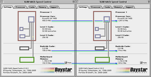
Here’s the before and after from a 933 MHz Quicksilver.
( “B” Quicksilver motherboard / Apple 820-1342-B )

Compare.png

Link describing the simple process:
 
Last edited:

Byrd

Well-known member
That's a nice little tweak thanks for posting. Has the clock crystal been removed? Slight overclock should be OK for the CPU but you might need good quality PC133 RAM to get it happy at 150Mhz FSB speeds I would think.
 

cobalt60

Well-known member
No way to gauge or confirm the speed increase at that time.
I ran into a similar problem of the OS reporting incorrect bus speed after overclocking my Sawtooth to 120MHz. Had to confirm with Macbench/Xbench (CPU benchmark was 20% faster, memory about that too).
 

MBongo

Active member
No. No clock crystal was removed. Just that simple little jumper and the addition of that resistor. It’s been running fine for 2 years with mixed 133 RAM on an “A” board. Haven’t tried it with a DP yet but may do so eventually. [Pretty happy with my “stock” 1 GHz DP QS for now.] And now this tweaked 933 rivals it?

Will see if it coughs when I replace that one 256 MB stick with a 512?

May possibly check with MacBench and/or XBench later…
but previously noted very little difference via QuickBench.
 

cobalt60

Well-known member
Apparently it did, but I was muddled anyway.
On the plus side, I am pretty sure PC150 exists, but is really rare (none on eBay searching "PC150 RAM").
I feel like homebrew PC150 shouldn't be too hard.

fwiw, my 120MHz bus Sawtooth would not boot with any of the PC100 I had.
 

Phipli

Well-known member
On the plus side, I am pretty sure PC150 exists, but is really rare (none on eBay searching "PC150 RAM").
I feel like homebrew PC150 shouldn't be too hard.

fwiw, my 120MHz bus Sawtooth would not boot with any of the PC100 I had.
I don't have much newer than the G3 era, so buying PC133 has always been the easy answer to removing RAM from the overclock equation. My beige, B&W and Pismo all have 133MHz RAM in them.
 

herd

Well-known member
All of the Digital Audio and Quicksilver computers I've seen worked fine at 150MHz bus, including whatever RAM they happened to have. I think most 7410 CPUs can handle it too, but my memory is foggy about the 7400. I think I tried it once, and I had to bodge a via (instead of simply move a resistor), but I don't recall the outcome. This was probably around 2007 too. Anyway, increasing the bus speed helps speed up most things, even if you have to lower the CPU multiple to keep the CPU speed the around the same. The firmware doesn't correctly report a lot of the different speed possibilities.
 

cobalt60

Well-known member
The firmware doesn't correctly report a lot of the different speed possibilities.
There is an OF variable you change to tell it the bus speed is 150MHz (or whatever speed you want). There was a somewhat widespread (and incorrect) belief in the past that this OF change was a software overclock, with multiple people saying "it feels faster".
 

herd

Well-known member
For fun, I dug out an old 450MHz 7400 CPU card from an AGP, moved a couple resistors, and plugged it into a Quicksilver. The 7400 chip seems to work fine at 150MHz bus speed, even though the datasheet indicates 100MHz as the limit. Naturally, the 7410 also has no problem at 150MHz (133MHz datasheet). I remember doing this mod on a few Digital Audio computers back in the day, because the 533MHz boards would usually do 600 (4x150 vs 4x133) by moving just one resistor.
 

cobalt60

Well-known member
It looks like a 4 position dip switch can be installed in that location. Is it possible to utilize that in this situation?

On the Sawtooth, there were 4 resistor locations (and how every many resistors in whatever positions for the desired bus speed, always 100MHz as sold) on the underside of the board. The resistors could all be removed, a dip switch added, and bus could be adjusted easily. There were various bus speeds ranging from 66MHz to 133MHz that could be set.

Just wondering if the same could be done here.
 
Last edited:

herd

Well-known member
I guess this info has been lost, because the usual internet searches can't turn it up anymore. Want to buy some floormats for your car or some prescription drugs? Woo progress!! So once more, lets rediscover it, again:

For bus speed settings on DA and Quicksilver (with 133MHz bus i.e. RAM to CPU speed), the IMI C5003 clock generator chip has inputs on pins 18, 19, and 20 that can configure the outputs. The datasheet describes the available settings, and the more interesting ones are 140MHz and 150MHz. On the logic board these pins have 10k ohm pull up from a nearby resistor pack (logic 1, one, to 3.3v) and are routed to the first three pins of the unpopulated S3 switch block. They also go to the 300-pin CPU connector. Yes, the CPU. Compare an apple 820-1175 CPU board to earlier ones and note R26, R27 and R42. Installing a "450MHz" CPU from an AGP Graphics or Gigabit Ethernet model (with 100MHz bus, so the CPU is set to 4.5x100MHz) straight into a DA/QS will show a faster speed in system profiler via the firmware calculations, but will actually still run at 450MHz (4.5x100MHz bus speed).

Try it: you can stick a completely stock AGP CPU straight into a Quicksilver, even though everyone will tell you that it won't work because of the different bust speed. Adding R26 to the CPU board will set the bus to 133MHz, and adding or bodging R42 (and moving or removing R26) will be 150. The other various DA and QS CPU cards all have these same resistor locations to configure the bus speed by altering the values on the inputs to the clock generator chip. The various aftermarket CPU cards also have them, so they all figured out this stuff too. There is no need to remove the logic board and kludge some dead short ground wires or super low value resistors to re-overide the settings coming from the CPU board. You could install a switch block on the logic board at S3, but then you'd be fighting the signals from the CPU board, so you'd want to remove the resistors there. But if you're setting up resistors on each different CPU board for the multiple, then might as well set the bus speed there too, right?

I think I first saw this info on Cubeowner circa 2003 when there was a discussion of overclocking the Cube bus (IMI SG500DYB) from 100MHz to 105, 120 or possibly 133, that expanded to include Quicksilver vs Mirror Drive Door (MDD) bus comparisons, all using the same G4 chips. This is the same clock generator chip used on the AGP Graphics and the Gigabit Ethernet models.

Anyway, this site has a good search function, so assuming it will be around a while here are some keywords that might help people later on: IMI_C5003 IMI_C5003.pdf C5003.pdf IMIC5003 IMIC5003BY Cypress INTERNATIONAL MICROCIRCUITS INC. www.imicorp.com Clock Generator overclock front side bus speed FSB datasheet 150MHz 140MHz quicksilver digital audio etc.

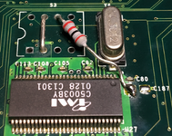
IMI_C5003.png
 

Attachments

  • IMI_C5003.pdf
    225.4 KB · Views: 7
  • SG500.203077.pdf
    62 KB · Views: 4
  • sg500.pdf
    92.8 KB · Views: 3

cobalt60

Well-known member
If anyone can't tell, my favorite thing to do with old Macs is overclocking bus speeds, so I really appreciate this post @herd. I was oblivious to these clock generators on G4s.
The other various DA and QS CPU cards all have these same resistor locations to configure the bus speed by altering the values on the inputs to the clock generator chip.
Are you saying these were actually populated on Apple CPU modules from the factory?

You could install a switch block on the logic board at S3, but then you'd be fighting the signals from the CPU board, so you'd want to remove the resistors there.
What do you mean by fighting? Is it the case that if SEL0 only was bridged on the MB, and SEL1 only was bridged on the CPU, it would effectively be the same as if SEL0 and SEL1 were bridged either only on the CPU or the MB?

Any idea what the 4th switch at S3 is for?

I just did a Google search, and apparently MDDs also have a place to install a switch block, with a user on Reddit getting 200MHz. Allegedly he installed a dual 7448 module and hit 3.6GHz?! Using "custom watercooling loop with TECs". Seems a bit unbelievable.

Any idea what clock generator the MDD used?

I also read "The Mac mini G4 has a 167MHz bus which can not be changed". Anyone know more about this? "can not" seems too absolute, I'm thinking it's more the case that no one tried, succeeded, documented it, and published the findings.
 

herd

Well-known member
With digital logic circuits the "0" or "1" is determined by the voltage. An input pin will usually have a high impedance, so it would take very little current to change the voltage one way or another. A typical solution to configure an input like this is to design the board with two resistor locations that connect the pin either to high voltage, or low. Then during assembly you would install a resistor in one of the two locations (pull-down or pull-up) to configure the input as either 0 or 1. To change it later on, you would *move* the resistor to the opposite location. What if no resistors are installed? What if both resistors are installed? What if the circuit is designed with 4 possible resistors?

You could think of it like a precision mechanical balance for masses. With both sides of the scale empty, it can easily tilt in either direction. You could walk past it or slam a door and the scale could wobble or shift one way or another. Its state is indeterminate. If you want it to clearly tilt to one side far enough to have a binary logic value, you could add a bean to one side; then it will tilt that way even if you blow on it or bump the table. If you move the bean to the other side, it will tilt the other way. If you don't want to move the bean, but you want it to tilt the other way, what would you do? You could put two beans vs the single bean, but would it tilt far enough to really call it a "1" or a "0"? How precise are your beans anyway? So instead you could add a brick to the other side and it would definitely tilt that way. Now what if you want to tilt it back towards the bean without removing the brick? You could add a gorilla on the same side as the bean. But what if the other side has been nailed down to the table?

So you could technically use a gorilla and a nail gun to set "0" or "1" no matter what the beans and bricks are doing, but I would not call it elegant and at some point the thing just breaks.

en.wikipedia.org/wiki/Pull-down_resistor
 

cobalt60

Well-known member
Moral of the story, don't use solder bridges or switches in place of resistors? I mean I knew it wasn't ideal, never knew it was as bad as a brick vs a nail-gun. I've just been following guides I've found on the procedure, I do not have an intimate understanding of electronic components.

Looking at the 604 overclocking guide by @Phipli, those have clear pull-up and pull-down locations. But for G4s, I've only ever seen pull-up positions changed. How is the pull-down handled with those? Or how should it be handled? I think I'm seeing that sometimes all of the pulldown resistors are populated, and then you can only worry about changing the pullups? If that's true, would it also be true on the 604 cards?

All of these G4 motherboards seem to be designed to accept a DIP switch. Is that not the case, and some different component is being install there at the factory? Or if it is the case, is Apple using them for only a short time that the lack of a resistor doesn't matter much? Or are there possibly resistors somewhere else on the board that allow a DIP switch to be used without issue? If not, my personal desire for a switch would just lead me to make a PCB to convert the DIP position to a surface mount DIP with resistors, or something along those lines.

What about the issue of CPU bus setting vs the motherboard bus setting fighting each other. I am not seeing how it would work at all unless the CPUs are simply never populated from the factory.
 
Top