cheesestraws
Well-known member
Multiple people have asked me recently about my bodge-up LC II PSU that I use in the rackmount LC II, so I'm going to post about it here. It comes hedged about with a number of warnings, though: this is amateur hour hardware, and may be a bad idea in ways I don't know about. Obviously this comes with no guarantees at all beyond my statement that I've built two of them and they're both basically stable (one is in use in my rackmount LC, the other I use to test boards with). I don't use them with machines with spinning discs in, though.
For most uses, the macATX or similar is a far better option that this, if only because someone's actually tested it properly. But availability of those varies over time, since they're enthusiast-type projects. That's just a fact of life for small-run hardware, honestly. But I would probably have used one of those if they had been invented at the time I was building the rackmount LC .
.
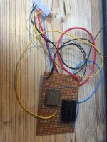
That said, part of the point of posting this is to point out that the LC boards at least are really not difficult to power; and while obviously using/repairing "real" PSUs is desirable to keep machines as near stock as possible, the loss of a power supply is by no means the end of the machine. And if you have spare LC boards you want to test, this is a reasonable way to do it. I just built this up on a veroboard for my own use, and it was quick and easy, and I am not good at this.
The approach I took is: take a standard 5V 2A wall adapter, because most of the load in my LC is on the 5V line. Then use two isolating DC/DC converters to generate +12 and -5v. +12v is easy; and actually it being an isolating DC/DC converter is overkill, but this is the part I ended up with after getting overwhelmed by choice, panicking, and buying the first thing that looked vaguely like it would do the job. To generate the -5V, I used an isolating DC/DC converter that takes 5V in and pushes 5V out, but the output is isolated from the input. If you then tie the positive side of the output to 0V, you end up with -5V.
Note that the -5V supply is only used, as far as I can see, for differential signalling on the serial ports. So if you don't want to use LocalTalk or RS422 devices, you can leave it off; RS232 devices will (probably) work fine, though I haven't tested it. Since the rackmount LCII is an AppleTalk router, the -5V is non-negotiable for my use case.
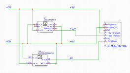
Here's a badly-drawn schematic:

The +5V and 0V (which I've just noticed the + on, argh) lines come from a barrel jack on the left in mine. The top converter, the 0512, is, as its name suggests, the 5V -> 12V converter; the 0505 at the bottom is, as its name suggests, the 5V -> 5V converter. These probably ought to have some RFI suppression capacitors around them; the datasheet for the REC3A-0505 provides suitable values. Since mine is running full time in what amounts to a Faraday cage, I didn't bother. Also, I was lazy.
Also, don't be put off by all the parameters/choices of the DC/DC converter. I aimed for something with roughly the current capacity of the PSU already in the machine, then narrowed down my selection by the highly scientific method of "picking the cheapest one that looked easy to solder and was also in stock on that day".
Hope this is useful to someone, anyway .
.
For most uses, the macATX or similar is a far better option that this, if only because someone's actually tested it properly. But availability of those varies over time, since they're enthusiast-type projects. That's just a fact of life for small-run hardware, honestly. But I would probably have used one of those if they had been invented at the time I was building the rackmount LC
That said, part of the point of posting this is to point out that the LC boards at least are really not difficult to power; and while obviously using/repairing "real" PSUs is desirable to keep machines as near stock as possible, the loss of a power supply is by no means the end of the machine. And if you have spare LC boards you want to test, this is a reasonable way to do it. I just built this up on a veroboard for my own use, and it was quick and easy, and I am not good at this.
The approach I took is: take a standard 5V 2A wall adapter, because most of the load in my LC is on the 5V line. Then use two isolating DC/DC converters to generate +12 and -5v. +12v is easy; and actually it being an isolating DC/DC converter is overkill, but this is the part I ended up with after getting overwhelmed by choice, panicking, and buying the first thing that looked vaguely like it would do the job. To generate the -5V, I used an isolating DC/DC converter that takes 5V in and pushes 5V out, but the output is isolated from the input. If you then tie the positive side of the output to 0V, you end up with -5V.
Note that the -5V supply is only used, as far as I can see, for differential signalling on the serial ports. So if you don't want to use LocalTalk or RS422 devices, you can leave it off; RS232 devices will (probably) work fine, though I haven't tested it. Since the rackmount LCII is an AppleTalk router, the -5V is non-negotiable for my use case.
Here's a badly-drawn schematic:

The +5V and 0V (which I've just noticed the + on, argh) lines come from a barrel jack on the left in mine. The top converter, the 0512, is, as its name suggests, the 5V -> 12V converter; the 0505 at the bottom is, as its name suggests, the 5V -> 5V converter. These probably ought to have some RFI suppression capacitors around them; the datasheet for the REC3A-0505 provides suitable values. Since mine is running full time in what amounts to a Faraday cage, I didn't bother. Also, I was lazy.
Also, don't be put off by all the parameters/choices of the DC/DC converter. I aimed for something with roughly the current capacity of the PSU already in the machine, then narrowed down my selection by the highly scientific method of "picking the cheapest one that looked easy to solder and was also in stock on that day".
Hope this is useful to someone, anyway

