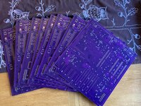
Trash80toHP_Mini Posted February 7, 2018 Author Report Share Posted February 7, 2018 (edited) All in good time, "reading" the GALs to determine if they're fused or registered is still pretty far off. First I'm socketing the CPU and the Crystal Can for the 32MHz test to see if this project is really worth the fuss. This is the bottom of three tiers, lowest cost Accelerator in MicroMac's lineup for the Compacts.. The GAL ICs functions just fine on 50MHz PowerCache Accelerators, so I expect them to shine when I clock the board for the 40MHz IIfx Processor test. I need to order a set of SMT PLCC-20 Sockets to install on my performer for use when the time comes to desolder my quintet. Even if they're registered, the logical operations will be apparent enough. Bolle has collected a lot of info on formulas for interfacing the 68030 to the 68000. Unlike Trekkers, we're treading where the Amiga fanatics have gone before! Edited February 7, 2018 by Trash80toHP_Mini page break continuity Quote Link to post Share on other sites
Trash80toHP_Mini Posted February 7, 2018 Author Report Share Posted February 7, 2018 (edited) I'm taking a second run at explaining what the "Agena Shield" does. I've illustrated a dual purpose combination SMT Pad/Thruhole footprint that allows either type PLCC Socket to be installed (hopefully) on Prototype or the QFP 68030 Agena Shield. A DIP strip socket/tall header board interconnect system for mounting Shield to Prototype also provides headers for attaching leads of Logic Analyzer. Same for the BGA socket/tall header setup, the headers plugged into the PGA 68030 Socket correspond 1:1 (crosses fingers) with the pads of the QFP 68030. A nice overhead shot of the SMT Socket with a size reference floated to the surface of the 'Bay, so I dragged it on board. Gotta find a nice Pic of the PGA socket, that gradient thing was an accident I left alone. Does anyone have a link to a REAL PostScript PDF data sheet for the QFP 68030? I need to snag the outlines and text for use in AI. Same for the PGA IC pinout. I HATE scanned in paper page images, they're awful. Unifying the Killy Klip/68000 leg interface with a Right Angle SE PDS Connector installed puts Agena vertical for easy probing The "NuBus" type connector is far more robust with additional power/ground lines, buffering and some strange voltages and clocks thrown in there too! The cutout necessary for SIMM Socket clearance make use of the setup in the horizontal impractical. It's gonna be open air testing on the bench for a while. That's the plan anyway. I've got two more pages to go in the GAL Coloring Book and a bit of GAL rearranging in the AI file to relax between connection buzzing sessions. I'm running on empty ATM, but I've got three days to rest up at work! Edited February 7, 2018 by Trash80toHP_Mini the usual Quote Link to post Share on other sites
IlikeTech Posted February 7, 2018 Report Share Posted February 7, 2018 Okay, does anyone know what the model number of the male version of the SE PDS connector is? Quote Link to post Share on other sites
Trash80toHP_Mini Posted February 7, 2018 Author Report Share Posted February 7, 2018 (edited) Here are some of the descriptions on pics I searched. I'll unearth DCaDftMF for what Apple called it in the spec if this isn't enough ksm Row 3 Male 96 pin Din 41612 Euro type 96P Plug R Type Vertical Euro DIN 41612 Connector Male ... VME Bus DIN Connector Mechanical Drawing, Board Connector ... Looks like the SMT 68030 has four more pins than the PGA 68030. Are they redundant power and ground pins in your schematic capture models? Comparing pinouts between types looks like a major PITA! Edited February 7, 2018 by Trash80toHP_Mini the usual Quote Link to post Share on other sites
Trash80toHP_Mini Posted February 7, 2018 Author Report Share Posted February 7, 2018 15 hours ago, IlikeTech said: Rev 2 with corrected names and the bus moved out of the way. Eagle has a 68881, but not a 68882, so I may have to make one. Ugh. Rev 2 Netlist.txt I like it! I can work with your conventional presentation as a DELTA Schematic, marking it up if the revisions don't match what I'm "seeing" in the PCB Trace modeling that works for the way my noggin' doesn't work quite right. Those who actually do electronics and digital development will be very glad to be able to read my crazy AI diagram Hieroglyphs in an actual, real world schematic diagram for a change. Thank you! As for the 68882, we don't need at all until we begin to close in on a near production level PCB design. Its pins should map 1:1 with the 68030, no? We don't want it cluttering up the DELTA Schematic. I'm only using it as a U2 placeholder in the component list for inclusion much later on in the process. Mapping differentiation in control lines where they are engulfed by the GALS, their exit points after they are tweaked or are synthesized (like A0)) within the GAL Maelstrom. Some merely skirt the whirlpool as they are monitored by the GALS (like A19, A20 and A21 I've yet to document in AI) and more exceptional cases I may find like /AS. /AS in its native 68000 state is monitored by U5 and is engulfed by U4 where there is a Logical disconnect. Within U4 it appears to be translated to a 68030 /AS state which is monitored by U6 on its way to the 68030. These two examples are what the DELTA Schematic is all about. If you pull those bus lines off the 68030 it would be a big help to me. Quote Link to post Share on other sites
Trash80toHP_Mini Posted February 7, 2018 Author Report Share Posted February 7, 2018 Quote Link to post Share on other sites
IlikeTech Posted February 7, 2018 Report Share Posted February 7, 2018 Cool! I will add to the schematic once I have a AI file because the connections are a little hard to read. have you verified my current schematic? Quote Link to post Share on other sites
Trash80toHP_Mini Posted February 8, 2018 Author Report Share Posted February 8, 2018 (edited) I thought I was ready to sign off on Rev.1 of your work, but I found a boo-boo I'd made while doing p.3 of the Coloring Book. U4 pin-4 connects to U6 pin-4. I may have had a short between pins 5 and six on U6 when I was buzzing the connections. Thought I'd had it figured out, but now that /AS on the 68030 remains connected to pin-5 on U6 there's no longer what seemed to have been a clear path. Final page of the Coloring Book covers U7. Edited February 8, 2018 by Trash80toHP_Mini Major mess up. ::) Quote Link to post Share on other sites
IlikeTech Posted February 8, 2018 Report Share Posted February 8, 2018 Better? Quote Link to post Share on other sites
Bolle Posted February 8, 2018 Report Share Posted February 8, 2018 I will be done with all connections to the GALs on mine tomorrow... Already curious how our two compare to each other. Quote Link to post Share on other sites
Trash80toHP_Mini Posted February 8, 2018 Author Report Share Posted February 8, 2018 (edited) Yep, me too! Can't wait to see how the control signal I/O mapping correlates with address monitoring and synthesization along with that magically appearing A0. Coloring Book p.5 GAL U7 scheduled for retro-tech arts & crafts playtime tonight. p.4 GAL U6 That Pink highlighted web is an interesting mix of inputs driven by CLK on 68000 pin-6. I'm not expecting a whole lot to be found connected to U7 as I've seen it unimplemented. I'll bet a shiny nickel that its main function is to fiddle with SE PDS pin A29. It's the first implementation I can imagine finding of what became the standardized 15.667MHz reference signal C16M in SE/30, IIci and IIsi. It's described as "gate array and IWM clock." What clock rate did the SWIM update use? I wonder if any of this explains that 25MHz crystal can curiosity on my 16MHz card? Delta Schematic error checking and further development will have to wait until I play around in AI and verify my own results. There are a LOT of n.c. pins to verify before I move on to error checking the signals/pinouts I've colored in. edit: can the connection lines be customized for color coding of the different buses in Eagle? Still need to pull that bus thing off the 68030 for clarity's sake if it's possible. Edited February 8, 2018 by Trash80toHP_Mini Quote Link to post Share on other sites
IlikeTech Posted February 8, 2018 Report Share Posted February 8, 2018 The bus is just something to contain all the nets so I don't have 32 address and data lines across the screen. Unfortunatly, you cannot change the colors of individual nets, no. Should I get started on implimenting page 4? If so, would it be possible to get proper pin numbers ? Quote Link to post Share on other sites
Trash80toHP_Mini Posted February 9, 2018 Author Report Share Posted February 9, 2018 Just ignore the coloring book, that's for my reference during downtime at work and for those who might like to look at unverified doodles of connection buzzing in progress. When I've got something bodged up in AI, I'll upload a PDF. It's too bad you can't do the color coding in Eagle, I'll have to build the Delta Schematic in AI using your presentation as a template to see the interactions. No biggie that, unlike the coloring book, there's no routing involved! Quote Link to post Share on other sites
Trash80toHP_Mini Posted February 9, 2018 Author Report Share Posted February 9, 2018 Too tired to go beeping about the board tonight, but I saw an interesting pattern in some n.c. results" some n.c. pins appeared to be clock inputs on GAL pin-1 I/CLK I was curious why those pins didn't connect to that PINK highlighter mess above pin-15 of the 68000: CLK (8MHz) It really struck me as strange that 68030 E1 - CLK (16MHz) is driven by pin-19 I/O/Q of a GAL? One mistake in tonight's drawing: 68030 CLK is driven by U6, not as marked at U5, oopsie! Managed to beep out (total lack thereof actually) some of the lines. NOTHING I connected in blue in that drawing tests positive for anything at all by the continuity meter? But they are DEFINITELY not connected to the 8MHz web, I checked that much after I got home. That 25MHz sampling rate thing is waaayyyy out there beyond WAG territory. Does a connection to an oscillator show up as open for some reason? Do some of the GALs not require a timing signal? Makes no sense . . . really tired . . . zzzzzzzzzzzzzz Quote Link to post Share on other sites
Trash80toHP_Mini Posted February 9, 2018 Author Report Share Posted February 9, 2018 ILT, I opened your Rev 1 Netlist in Wordpad this time and the tables look great. It was a jumbled mess when Rev 0 opened in Notepad. Can you export a list of connections. For the diagram above we'll call the 68000 U0 and we'd see something on the order of: U0 15 - U4 3 U0 15 - U5 1 U0 15 - U6 1 U0 15 - U U0 15 - U U0 15 - U Quote Link to post Share on other sites
Trash80toHP_Mini Posted February 9, 2018 Author Report Share Posted February 9, 2018 (edited) I could try morphing AI trace visual thinking and attempt to learn to use conventional schematics? I can format a TXT representation of the connections from any given Coloring Book page I do. I upload TXT so you could import that layer's connections into an Eagle file? Doing it manually from a home grown TXT format will do. Eagle does multiple board layers, but how many? Are layers color coded? Doesn't really matter as I can use a series of separate Eagle files like the ones you've posted pics of to build oodles of color coded layers in AI. PCB layout packages are for knitting together information you already have into something you can use to make a board. We'll be turning the board layout process around for use as PCB reverse engineering tool to generate board layout information from a PCB in hand. My end in plain TXT, your end bolded: Build my board components model in AI Print Coloring Book Pages Buzz connections between pins, "coloring" the page Translate visual trace mapping from Coloring Book Pages into formatted TXT Build PCB layout package schematic from the page TXT Print/Post schematic verification/markup Make corrections, if any as needed (repeat these three steps as necessary) Place verified Schematic Diagram into AI as a template Build connections from that Coloring Book pagein an AI Layer Break (Coloring Book Page) layer out into color coded layers for different views: --- individual signal trace pathways --- individual IC trace connections --- things like my GAL Maelstrom (see below) --- whatever You'd be generating subsets for me while building your full card Schematic Capture. I've pulled out the file on Protected PAL/GAL Reading. I'm wondering if posting the equation development for a given GAL within that component in a Coloring Book page would help in unraveling the logical operations between components? I'll build an example of that tonight. It will definitely help me wrap my head around that process. Me loves scalable vector graphics for crap like this! Edited February 9, 2018 by Trash80toHP_Mini the usual Quote Link to post Share on other sites
Trash80toHP_Mini Posted February 9, 2018 Author Report Share Posted February 9, 2018 (edited) Nightmare scenario: Bus multiplier is generated in GALs and limited to 2 x 8MHz = 16MHz Prevents upgrading a low end accelerator by simple Crystal/CPU swap. Edited February 9, 2018 by Trash80toHP_Mini the usual Quote Link to post Share on other sites
IlikeTech Posted February 9, 2018 Report Share Posted February 9, 2018 UMM. That sounds good. You give me a TXT file and I will convert it into eagle. In this version, it only supports 2 layer boards. If I crack it then maybe more, but I don't like doing that. Is the multiplier actually generated in the GALs? Quote Link to post Share on other sites
Trash80toHP_Mini Posted February 9, 2018 Author Report Share Posted February 9, 2018 (edited) Dunno, one of our boffins will need to answer questions about clocks, bus multipliers and the magical abilities of GALs. But from the looks of that nasty fat PINK vericose vein on my diagram (that's shown as connected to the wrong GAL. ) that may be a most unfortunate circumstance. If it was done intentionally to prevent simple CPU upgrades, maybe the GALs and Crystal Can can be tweaked to support multipliers for 32MHZ and 40MHz? This whole thing did give me a notion about developing a second shield for degubbing and emulating multiple GAL setups like I am messing around with and Bolle is actually working on! Edited February 9, 2018 by Trash80toHP_Mini spellchecking Quote Link to post Share on other sites
Trash80toHP_Mini Posted February 11, 2018 Author Report Share Posted February 11, 2018 Just had a blast playing around in Illustrator! Not finished, page 5 on U7 yet to go, not fully verified, but almost ready to start that process. . . . and a .PDF for anyone who cares to take a closer look: 4PAGES.PDF Quote Link to post Share on other sites
IlikeTech Posted February 11, 2018 Report Share Posted February 11, 2018 Nice work! This is all the connections in one file? Quote Link to post Share on other sites
Trash80toHP_Mini Posted February 11, 2018 Author Report Share Posted February 11, 2018 (edited) THX. It's every connection from Coloring Book pp.1-3 and what I've got done from p.4 U6 in a layered, color coded AI file. I pasted everything into a single layer in a new file to save this PDF. I'll build a visual color key and four(?) simplified PDF views by function this morning. Apple Green + GAL Maelstrom Red = Maelstrom's odd 8MHz clock web (still looking for 25MHz web) Black = control signals sucked into the GALs, never to emerge. /AS connected to Maelstrom U5/U4 connection Magenta = Control Signals that are only monitored by the Gals, some connected to multiple Gals Orange = Address lines that are only monitored by the Gals, some connected to multiple Gals THICK TRACES = 68030 Signals Synthesized within in the GAL Maelstrom that aren't present on the 68000 pinout This represents DELTA Schematic Rev.3.5, anything not indicated in DELTA should be 1:1 and I'm not concerned at all about that. That's housekeeping, DELTA is the realm of the mystical magical! If you can build an eagle file for each view by functional diagrams to follow and I can verify my connection buzzing for verification/markup from those representations. It's impossible to proofread one's own copy, TXT or visual. One can find/correct many errors, but a second/third set of eyes can catch almost all of them. A few will inevitably make it into publication. Gotta figure out a way to buzz the 25MHz clock lines, at this point that [*~}\^|%] crystal can looks like a red herring! If the board is hardwire limited to simple clock doubling, it's less attractive for the Compacts., but would perfect for doubling the PB100/Luggable 16MHz baseline for a 33MHz SMT 68030/6882 combo. Bolle's VMemRAM board daughtercard could be a viable option for the Luggable. Inevitable Edit: Clarification-Grammar-Spellchecking Edited February 11, 2018 by Trash80toHP_Mini the usual Quote Link to post Share on other sites
Bolle Posted February 11, 2018 Report Share Posted February 11, 2018 I have been busy as well... Was going through the nearly unreadable schematics for the c't PAK/3 and started to recover them and fill in the gaps that those tiny images I found on the net have. There are only 5 GALs and two buffers on there. -GAL1 is the 030 clock state machine -GAL2 is a cache controller -GAL4 & 5 are the 68000 bus state machine -GAL6 is the address decoder -GAL3 - actually a 6th GAL - can be used for switching between 68000 and 68030 The PAK features 32K zero wait state Cache and space for a copy of the SE ROMs right on the faster 030 bus. The neat thing about the PAK is that I have all the jedec files right here Have been restoring all the signals present on the GALs now so far: And the obligatory 68000, 68030 and 68882 connections: The address and data bus are the same as on my accelerator - no surprise. 68000 control bus signals that do not connect directly to their 030 counterparts also are exactly the same as on the Total Systems accelerator. The signals present on the GALs also look very familiar compared to what I buzzed out. Quote Link to post Share on other sites
Trash80toHP_Mini Posted February 12, 2018 Author Report Share Posted February 12, 2018 5 hours ago, Bolle said: There are only 5 GALs and two buffers on there. -GAL1 is the 030 clock state machine -GAL2 is a cache controller -GAL4 & 5 are the 68000 bus state machine -GAL6 is the address decoder -GAL3 - actually a 6th GAL - can be used for switching between 68000 and 68030 Sweet! Sounds fabulous. "030 clock state machine????" What's up with that damn 25MHz clock on mine??? Can GALs be used to set a clock multiplier? I'll be posting what I have worked out in diagrams sorted by functional later. Quote Link to post Share on other sites
Trash80toHP_Mini Posted February 12, 2018 Author Report Share Posted February 12, 2018 (edited) OK, here we go, it's enough to start comparisons withBolle's board and for me to finish degubbing/verification. I hope this helps somebody visualize what's going on within the GALS of my card. To me this isn't gibberish, it's a snapshot album of the functional blocks in my visual schematic: This is what I've got so far with color key. This is the GAL Maelstrom, all the signals I've found so far that pretty much stay within the GALS These are the only address line's I've found so far that are monitored by the pins of Gals on their way to the 68030 Likewise these are the only control line's I've found so far that are monitored by the pins of GALs on their way to the 68030 This is where it gets really interesting, these control lines are sucked into the whirlpool to emerge or not at is whim, in whatever form. I have to nail down what's going on with /RW, found an exit (error?) but no entry point. /AS emerges with a large logical disconnect across several GALS. The 16MHz Clock for the 68030 is the major thorn in my side, we'll see. What's really cool would be the three signals for the 68030 that the GALs synthesize from 68000 signals, where they missing entirely from the 68000 bus. This is a shorthand version of everything that hits the 68030 in the Delta Schematic. The four address lines were stubbed out and labeled at the source, seeing them wend their way through the legs of the GALS was distracting. Other than what I find by the time I'm through with the rest of U5 and done tangling with U7 and that [&*()&$#] 25MHx Crystal Can, we can pretty much assume everything else is connected 1:1 from 68000 to 68030. We'll see. Speaking of crazy timings, here's what I've got so far. Lemme know if this stuff is helpful or not, I've had feedback both ways in the past and I'm curious how about how the heads of others put things together/take 'em apart. This way works for me. Lets see if it works better in a series of diagrams out of Eagle broken down by function in the layers of Illustrator or the like. Edited February 12, 2018 by Trash80toHP_Mini the usual Quote Link to post Share on other sites
Recommended Posts
Join the conversation
You can post now and register later. If you have an account, sign in now to post with your account.