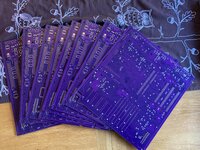
goncalo Report post Posted June 16, 2016 (edited) Hello from Lisbon Although this is my first post, I’ve been visiting this forum looking for clues on what might be wrong with a 1991 Macintosh Classic. I’ll try to clearly describe what happened so that owners with similar symptoms will be able to repair their Classics. I have no experience in electronics so please be patient and use a descriptive language for troubleshooting. I bought it knowing it didn’t work. The early symptoms were: No screen No disc activity No bong or any noise whatsoever Power cable was working I proceeded to remove the rear cover and noticed that, although it had been repaired in the past – some of the Analog Board capacitors were replaced – it was in general mint condition. The keyboard keys still had the mould texture so I guess it just stood in a corner, not being used. The insulator vinyl was missing as were all four plastic clips. It included the 40MB SCSI HDD (it spins and sounds “normal” when connected to an ATX power source) and a full 3MB memory expansion board. The Logic Board capacitors were still the original ones. I did noticed some mild electrolyte spilling – which I carefully washed away – but decided not to replaced them while I was troubleshooting the booting problem. With the rear cover off, connected to the power outlet and switched on, I could feel some warmth with my hand over some points in the back of the analog board, mainly near the flyback transformer and the QP2. While tinkering with a digital multimeter, near the QP2 transistor, I caused the fuse to blow. After that accident any fuse would blow once I attempted to turn the Classic on. Following this thread: https://68kmla.org/forums/index.php?/topic/22946-macintosh-classic-keeps-blowing-fuses/ I proceeded to replace: QP2 - transistor - original: CET 48C0 CEF02N6 - replaced with: IRFBC40 CP23 - blue ceramic capacitor - original: HR R 27 IJ 2KV - replaced with: (I will see it when I get home) RP40 - resistor - original: Red Red Brown Gold (220 Ohms 5%) - replaced with: (I will see it when I get home) DP5 - rectifier - original: BYT03 300 C039 - replaced with: (I will see it when I get home) I also replaced the usual bunch of capacitors: (The only reference I had was based on the previous values installed, please inform if you find any abnormal values) CP2 - 470uF - 35v - 10mm - 105° CP6 - 1000uF - 25v - 10mm - 105° CP7 - 1000uF - 25v - 10mm - 105° CP8 - 2200uF - 16v - 13mm - 85° CP9 - 470uF - 25v - 10mm - 85° CP10 - 470uF - 25v - 10mm - 85° CP12 - 1000uF - 25v - 10mm - 105° CP36 - 1000uF - 16v - 10mm - 105° As a result of these replacements I’m back to square one. The fuse no longer blows but there’s no action whatsoever. Yesterday I looked at Larry Pina’s 1993 edition of “Repair and Upgrade Secrets”. In the section dedicated to the Classic’s Analog Board troubleshooting (chapter 9, page 174) he mentioned the RP2 surgistor (?) could be at fault. 12 Ohm=good, 0.0L mOhm=bad. But I don’t know how to use the Digital Multimeter to test this. I resoldered it, but to no avail Additional Data Analog Board: 820-0395-C, 240V, wired JP1 jumper. I attached a picture of the back of the analog board after having removed the bad capacitors and giving it a thorough clean. What can I do now? Do you have any idea/procedure I could try? It’s so sad to see this beauty of a computer standing there, dead. I would love to hear from this community. Thanks Edited June 16, 2016 by goncalo Share this post Link to post Share on other sites
fri0701 Report post Posted June 16, 2016 (edited) Hi goncalo, I'm not too experienced with the Classic in particular, but I'll try to come up with some more stuff you can check. First of all, it would be useful to know the voltages (if any) being outputted. I don't know offhand the output configuration of the Classic, but I'm sure it exists online. Checking the voltages would show if there's an issue with the voltage not being sufficient, or if an issue exists that results in no voltage at the output. Capacitor-wise, the general rule for replacement (as I understand it) is to keep the capacitance around the same value, and have the voltage of the replacement be greater than or equal to the original. I think you're probably in the clear there. If you're handy with soldering (as you seem to be), another set of things to check would be any other transistors or diodes, especially those in higher-voltage areas. Make sure they aren't shorts or breaks. Transistors can be checked with a diode checker, depending on the type. This article explains it pretty well: http://www.vetco.net/blog/?p=184 Hopefully some members more well-versed in Classics can help you more specifically. This is just the general approach I use when I work on power supplies. Kudos on spending this much effort on getting things working. I'm in the same boat with an Apple /// at the moment Good luck! -fri0701 Edited June 16, 2016 by fri0701 Share this post Link to post Share on other sites
goncalo Report post Posted June 16, 2016 Hello fri0701. Thank you for your suggestions I tried to verify the outputs at the external floppy drive port but I got no readings at all. Just for reference, I did the procedure as suggested in the book I mentioned before (chapter 8, page 162): Black probe on ground Red probe on: Pin 5 (sixth on top row from the left) - -12V (-13.00V to -11.30V) - reading: 0.00 Pin 6 (fifth on top row from the left) - +5V (4.85V to 5.15V) - reading: 0.00 Pin 8 (fourth on top row from the left) - +12V (11.90V to 12.80V) - reading: 0.00 Based on these observations I'm assuming the problem is in the first stages of the power supply. Correct me if I'm wrong, but I'm assuming that problems in the Logic Board will not prevent the Classic from booting - is this true? It will only produce artefacts and other abnormalities in the screen - but it will boot. Are there any spots on the back of the Analog Board where I can verify the voltages? As suggested I will be checking other components - thanks for the link! I will be looking at it. Cheers! Share this post Link to post Share on other sites
goncalo Report post Posted June 17, 2016 (edited) So. Here are the components I tried to list previously: QP2 - transistor - original: CET 48C0 CEF02N6 - replaced with: IRFBC40 CP23 - blue ceramic capacitor - original: HR R 271J 2KV - replaced with: B 271K 3KV (270pF 3000V) RP40 - resistor - original: Red Red Brown Gold (220 Ohms 5%) - replaced with: Red Red Black Black Brown (220 Ohms 1%) DP5 - rectifier - original: BYT03 300 C039 - replaced with: BY399 800V 3A Edited June 17, 2016 by goncalo Share this post Link to post Share on other sites
goncalo Report post Posted June 28, 2016 Follow up I'm still looking at troubleshooting this Analog Board problem. But, while trying to list it’s components I've stumble upon some I just cant figure out what they are. The RP2 “surgistor” (Line Filter section?). There is nothing written on this component – I have no idea how to replace it. Some big resistors near the fuse have four color bands I cant find in any modern calculator. The last band on a four band resistor is supposed to be for tolerance, but these are yellow and no chart has yellow in the tolerance column. You can find these in positions RP13, RP18, RP19 and RP46. Could someone give me a hand? Share this post Link to post Share on other sites
techknight Report post Posted June 28, 2016 (edited) Alright. Your not gonna shotgun this thing unless you replace every part that exists on the board. You had mentioned that you have no experience with electronics, that scares the hell out of me, as this is a high voltage high current analog circuit with enough lethals to it to kill you. Also, you need troubleshooting and repair experience to locate the failed components and fix this thing. I am totally not against people learning electronics, but starting with this is like starting with the golden gate bridge with no experience as a structural engineer, and told to recalculate the load and replace the necessary weak points. ummmm... yea To learn electronics, you have to start with the basics, and start simple. You need to learn basic theory and operation, and then learn troubleshooting and repair. Electronic project kits, etc... Unfortunately I think your in over your head on this one and might need to send it to someone who CAN fix it. If you fix it, then awesome! but I am merely stating reality here. Edited June 28, 2016 by techknight Share this post Link to post Share on other sites
goncalo Report post Posted June 29, 2016 (edited) Thanks for your advice TechKnight. I've been having a lot of fun trying to grasp the essentials to handle this analog board. Most of what I know came from this forum and a lot is coming from your videos. This analog board seems to be the perfect playground for a curious guy since it's not that complex. I've looked at more modern boards such as the ones from the G3 iMacs (gosh) and comparing to those this is but a baby board. Right now I'm looking at the schematics from other analog boards (Macintosh and SE?), trying to establish parallels from them — understanding its workings and underlying concepts . And because I live on the other side of the lake, sending this board to you or to Uniserver might be somewhat expensive Edit: This video is particularly interesting: https://youtu.be/9B6F9IaMTf0 Edited June 29, 2016 by goncalo Share this post Link to post Share on other sites
techknight Report post Posted June 29, 2016 (edited) All I am saying, is be careful. BTW, about that video, Yea I need to hurry up and finish that series. I had since located the problem and fixed it, just need to finish recapping it. But I cannot remember if I uploaded the footage of the fix. Edited June 29, 2016 by techknight Share this post Link to post Share on other sites
goncalo Report post Posted July 1, 2016 BTW, about that video, Yea I need to hurry up and finish that series. I had since located the problem and fixed it, just need to finish recapping it. But I cannot remember if I uploaded the footage of the fix. Being a GOT fan, I'm used to cliffhangers… Happy to know you found the problem! Share this post Link to post Share on other sites
marcelv Report post Posted August 30, 2016 (edited) Follow up I'm still looking at troubleshooting this Analog Board problem. But, while trying to list it’s components I've stumble upon some I just cant figure out what they are. The RP2 “surgistor” (Line Filter section?). There is nothing written on this component – I have no idea how to replace it. Some big resistors near the fuse have four color bands I cant find in any modern calculator. The last band on a four band resistor is supposed to be for tolerance, but these are yellow and no chart has yellow in the tolerance column. You can find these in positions RP13, RP18, RP19 and RP46. Could someone give me a hand? RP2 is a surgistor, protects your mac by eliminating the destructive turn-on currents. You can measure it on the board has to be around 20 ohms The resistors in your picture are: RP1 22K 3W RP44 22K 0.25W RP13 100K RP14 220K RP18 220K RP19 220K RP46 470K looks like RP13 in your picture is damaged, you cannot measure it on the board because it's connected to capacitor . desolder 1 leg of the resistor and measure the value. RP1, RP14, RP44 and RP46 can be measured on the board and on my board have a reading around the indicated value. Only measure the resistors when the board is not connected to the power List of other resistors you can measure on the board: RP15 7K5 RP30 7K5 RP6 4K7 RP7 10K RP11 920 RP17 3K9 RP4 200 RP3 6K8 RP23 560 RP24 560 RP27 20K The capacitor list has different values than my board, but maybe it's a different board version. CP2 - 1000uF - 35v - 13mm - 105° CP6 - 2200uF - 10v - 13mm - 105° CP7 - 1000uF - 10v - 10mm - 105° CP8 - 2200uF - 16v - 13mm - 85° CP9 - 470uF - 25v - 10mm - 85° CP10 - 470uF - 25v - 10mm - 85° CP12 - 1000uF -16v - 10mm - 105° CP36 - 2200uF - 10v - 13mm - 105° Hope this helps, can supply more measurements if needed Edited August 30, 2016 by marcelv Share this post Link to post Share on other sites
goncalo Report post Posted October 3, 2016 Hello Marcelv Thanks for your input! Unfortunately I've been away from this project and was unable to properly reply to your post. I'm preparing a list of components to buy and I'll be verifying these values in the meantime. Thanks! Share this post Link to post Share on other sites
RodCastler Report post Posted October 29, 2016 Hi there, Please allow me to join you since I'm on a similar situation with a mac classic and I'm currently troubleshooting the analog board as well. Symptom: 5 volt line reads 5.00v but drops to 4.1v under 1A load. 12 volt line reads 11.54v and drops to 9.47 under 1A load. (I'm using an electronic load for testing. Using the Hard Drive as a load doesn't drop the voltage that much but is surely not enough to even spin the drive) HDD was tested to be OK on another mac. What I have done: - I have recapped the suggested CP line (after which, power-up time went down from 80 seconds to 3 seconds. This was the original symptom). - Large 200v cap measures spot on. - I have already tested the mosfet to be not-shorted. - Temporarily replaced a suspect optocoupler (with a 4n36) but results won't vary. - Diodes measure OK. Next step: Measure every resistor in the RP line as suggested above. Any other suggestions? Share this post Link to post Share on other sites
RodCastler Report post Posted November 4, 2016 I'm running out of suspects. All of the resistors and remaining caps measure OK, as well as the diodes, the voltage regulator and several other main components. ... and I still have the voltage-out of spec issue, that drops under load. This is measured without the motherboard installed. Today I performed a test: While powered with the defective smps, I artificially injected +5 and +12 to the board and my friend wakes up with a VERY wobbly and noisy screen. Next step: "Classic Mac Repair Notes" mentions a crowbar SCR Q8 that I will check tomorrow, although I don't think the issue is there. Share this post Link to post Share on other sites
bibilit Report post Posted November 4, 2016 Probably a bad opto oscillator, see here: https://68kmla.org/forums/index.php?/topic/27626-classic-ii-analog-board-no-output/ https://68kmla.org/forums/index.php?/topic/26555-analog-board-with-voltage-too-low-then-too-high/ Share this post Link to post Share on other sites
RodCastler Report post Posted November 5, 2016 Probably a bad opto oscillator, see here: https://68kmla.org/forums/index.php?/topic/27626-classic-ii-analog-board-no-output/ https://68kmla.org/forums/index.php?/topic/26555-analog-board-with-voltage-too-low-then-too-high/ Thanks! Actually the optocoupler is the very first thing I replaced after the re-cap. I used a 4n36 since I'll have to wait a few months before the exact part makes it to where I live: no local stores carry such part. I wonder if a 4n36 is at least a good replacement for testing purposes... Share this post Link to post Share on other sites