• Updated 2023-07-12: Hello, Guest! Welcome back, and be sure to check out this follow-up post about our outage a week or so ago.

SRAM for Portable "on sale" at DigiKey

LaPorta

Well-known member
How many would one need per design? Have his boards been made/are being made?

I would want one of these badly (provided they are for the non-backlit portable).


trag

Well-known member
TechKnight made several of them a few years back.  Ultimately, he did not want to continue the effort.  I think he may have passed the design on to someone else to produce, but I'm not sure of the status.    The boards went up to 8 MB, I think, so that would be four chips per board.  There's a couple of good threads following his design process and then sales around here somewhere, I think.

Ah, here we go: 


I'll go alert Maceffects, since he took over the effort.

 
Last edited by a moderator:

techknight

Well-known member
MacEffects has been working on this project. He just received in prototypes of the card, havent been tested yet, I dont think. 

He will be spearheading the project going forward and likely releasing something to market? Not sure of his plans. But as far as I am concerned the design is public domain. 

@maceffects

 
Last edited by a moderator:

Gorgonops

Moderator
Staff member
What technique did you use, the "anchor a corner, flood the pins with solder, clean it up with a braid" approach, or something more sophisticated?


maceffects

Well-known member
Sorry for not posting about this project before, I wanted to at least get the prototype ready and wait until techknight wanted to disclose he shared the designs with me.  I have sourced enough new old stock genuine Toshiba SRAM to provide us with 75 cards.  I'll be offering them for sale once the prototype is fully tested within next couple days and make some small revisions.   Each card will properly attribute design credit to @techknight's work in 2014. 

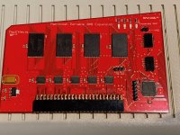
Here is a photo of the prototype, I need to adjust the package size of the capacitor in green.  And as you can see the card is ready to be tested once the battery for the Mac Portable is charged.  Next I'll search for the right jumpers and something good for connecting to the address strobe pin.  I'll start a thread somewhere once I have everything finalized. 

60989620700__C25BBE10-054A-4FE4-B20D-6E13B28879D0.jpeg

60975408074__554A59B4-17B1-488E-838C-E0E049D3E461.jpeg


Gorgonops

Moderator
Staff member
For laughs I modified the GAL code I came up with in another thread (repairing an original 1MB card) so you could use a 22v10 to make a jumper-selectable 7/8MB card using those Cypress chips. If someone wants to whip it up in Kicad the code is yours, no warranty expressed or implied.

(It compiles successfully in GALASM, that's it.)

Code:
GAL22V10  ; memory decoder
MACTHING   ; done

NC A20 A21 A22 A23 LDS UDS RW AS 8MEG NC GND
NC 245DIR 245OE MEMCS0 MEMCS1 MEMCS2 MEMCS3 RAMOE RAMWEHI RAMWELO NC VCC

245DIR = RW

/245OE = /RAMOE +
         /RAMWEHI +
         /RAMWELO

/MEMCS0 = A20 * /A21 * /A22 * /A23 * /AS
        + /A20 * /A21 * /A22 * A23 * /AS * 8MEG

/MEMCS1 = A21 * /A22 * /A23 * /AS

/MEMCS2 = /A21 * A22 * /A23 * /AS

/MEMCS3 = A21 * A22 * /A23 * /AS

/RAMOE = /MEMCS0 * /UDS * RW
         + /MEMCS0 * /LDS * RW
         + /MEMCS1 * /UDS * RW
         + /MEMCS1 * /LDS * RW
         + /MEMCS2 * /UDS * RW
         + /MEMCS2 * /LDS * RW
         + /MEMCS3 * /UDS * RW
         + /MEMCS3 * /LDS * RW

/RAMWEHI = /MEMCS0 * /RW * /UDS
          + /MEMCS1 * /RW * /UDS
          + /MEMCS2 * /RW * /UDS
          + /MEMCS3 * /RW * /UDS


/RAMWELO = /MEMCS0 * /RW * /LDS
           + /MEMCS1 * /RW * /LDS
           + /MEMCS2 * /RW * /LDS
           + /MEMCS3 * /RW * /LDS

DESCRIPTION

; Decoding logic to make a 7 or 8MB Portable memory card
; IF "8MB" is high card will put memory from 100000-8FFFFF
; Otherwise RAM decodes at 100000-7FFFFF
; Design uses chips in 8 bit * 2MB mode; organize as 2 4MB*8 bit banks
; with 74AC245 buffer on each data bus. Buffer address lines with
; 74AC244s


techknight

Well-known member
What technique did you use, the "anchor a corner, flood the pins with solder, clean it up with a braid" approach, or something more sophisticated?


Tacked it in place to align it, and then soldered the pins via drag soldering. 

 
Last edited by a moderator:

IlikeTech

Well-known member
Drag soldering works pretty darn well actually, the trick just seems to be LOTS of flux.  I managed to drag solder 2 TQFP-100 ATMEGA640 chips on a board I designed.  Worked fine.  Having the right kind of soldering tip helps a lot too.


Trash80toHP_Mini

NIGHT STALKER
I wonder how much of the power budget is conserved by using the four later tech ICs on your card vs the 32 SRM50256LM10 ICs on my Apple 630-4176 Boards? It's been so long I don't even remember the capacity of my boards?

 
Top