• Updated 2023-07-12: Hello, Guest! Welcome back, and be sure to check out this follow-up post about our outage a week or so ago.

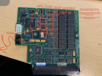
SE/30 with Micron Xceed Grayscale & Socketed Daystar Acceler

JDW

Well-known member
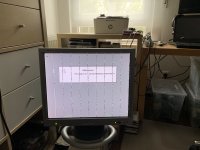
has it done this every since you got it, or is it something that just popped up one day?
Ever since I got it, from the very first time I powered it on. But of course, this machine was previously owned by someone else who really didn't know how to use it. I acquired it from them on Craig's List. And I don't know if they were the original owner. Due to their lack of knowledge, perhaps not. Especially since they sold me the SE/30 with socketed Daystar accelerator and this Xceed video card (with grayscale card) for a mere $75 at the time (if memory serves me correctly).


JDW

Well-known member
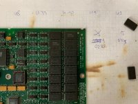
Here's another photo I just shot, showing some of the 16 VRAM chips on the Micron Xceed video card, from the side:


The photo illustrates just how difficult it would be to desolder even one chip, let alone all 16. Note how the solder point for each pin sits directly beneath the chip!

Some will tell me, "just use a desoldering heat gun." I have a heat gun for heat-shrink tube (which is like a hair dryer), but it's not made for desoldering chips. Furthermore, there is high risk of damage to the PCB if a heat gun is used too long on the board.

Others may suggest that I use an XACTO knife to slice off all the pins of the bad chip at the top of the chip, then easily desolder. You're right, that would work, but soldering on a replacement chip would still be impossible using a normal soldering iron.

Even if I knew which chip (assuming the culprit is indeed a single VRAM IC), safely desoldering it and resoldering a new chip is no simple task.


uniserver

Well-known member
:cool:

Here's another photo I just shot, showing
cool nice photos

The photo illustrates just how difficult it would be to desolder
maybe for you.

Some will tell me, "just use a desoldering heat gun." I have a heat gun for heat-shrink tube (which is like a hair dryer), but it's not made for desoldering chips. Furthermore, there is high risk of damage to the PCB if a heat gun is used too long on the board.
ok boss

Others may suggest that I use an XACTO knife to slice off all the pins of the bad chip at the top of the chip, then easily desolder. You're right, that would work, but soldering on a replacement chip would still be impossible using a normal soldering iron.
i wouldn't suggest that.

Even if I knew
well there you go, focus your effort and try and find out what one.

maybe pull the card and pay an experienced electronics professional to find out for you.

The other option is just leave it be,(just a slight line) and just enjoy it. Stop being a stickler.

--------------------------------------

Any experienced electronics professional with a digitally temperature controlled hot air re-work station could work on that with no issues.

Here is a 10pack for 39.00

http://www.ebay.com/itm/MT42C8128-DJ10-10pcs-42C8128-MT42C8128-ICs-IC-MT42C8128DJ/251331865419?_trksid=p2045573.m2042&_trkparms=aid%3D111000%26algo%3DREC.CURRENT%26ao%3D1%26asc%3D20001%26meid%3D4081701049397337309%26pid%3D100033%26prg%3D8920%26rk%3D1%26rkt%3D4%26sd%3D251331865419%26

if you really are interested in finding out what ram chip is bad, using an upside down duster, spray each chip and see if it goes away. the extreme cold, is what you need to create a significant diagnosable reaction.


trag

Well-known member
So, I was giving this some more thought....

And every avenue of investigation I came up with involved potentially dangerous (temporary) board modifications, because so many things are unknown. For example, one could tie the Chip Enable (CE_) pin on a single memory chip high and see how that affects the image on the screen. That would just require a temporary wire from 5V to the CE pin of a memory chip. The problem with this technique is that at some point a component on the card is going to be trying to sink that line low, and too much amperage to sink, could potentially damage the driver trying to pull it low. Once could pull it high through a resistor, but how much is enough to keep it high, without overloading the driver?

So, probably not a good idea.

But here are a couple of simpler, less invasive ideas....

Check continuity between all of the memory chip CE_ pins. If you find them tied together in some fashion, then that tells you which memory chips are working together as a bank. That's a small start. If they're all separate, then this is a largely useless exercise.

I can't remember if the chips have RAS lines as well, but if they do check those or whatever control lines would be used to signal a read operation and see how they are grouped amongst the memory chips.

Use the oscilloscope to probe the CE_ pins during different resolution depth settings. This will tell you whether all banks of RAM are always used, or whether some are not needed for some resolutions.

Does the oscilloscope you have access to have two or more channels?

Create a pattern of alternating light and dark rows of dots on the screen. Then probe various data pins on the memory chips to see if they're synchronously high and low, or alternating with each other. This will give you some idea of which pins are contributing which rows of data. If you find a pattern, and then test the pattern until you find a break in the pattern. The pin you're probing when you find the break is your likely culprit. If there are no breaks in the pattern, then either you need a different pattern (invert the light and dark dots, e.g.) or the problem is downstream of the memory chips in the buffers which are used to deliver the data to the DACs in proper order.


Bolle

Well-known member
Six years later nearly to the day the card made it onto my workbench...

Quickly traced out how all those muxes are connected:

IMG_1780.jpg

It is either a stuck serial output on one of the VRAMs or a broken input (and maybe output - not sure yet) on one of the 2:1 muxes.

I think I will desolder the muxes first to run them through the chip tester because they are easier to get on again.

No broken traces to be found between VRAM and 257s muxes, so it has to be a (partly) failed IC somewhere.


Bolle

Well-known member
Hm, scratch that. It can't be a completely dead output on one of the VRAMs either. Was randomly pulling down some output lines on a few chips and was getting more than one line on the screen each time.

Can a portion of the serial output memory inside the VRAM go bad? That's actually the only thing that would remotely explain a single vertical line for me right now... :?:

Don't have a donor card for VRAM chips here, but got one on my eBay watchlist. Might just replace all the VRAM and see what happens.

(actually I do have a possible donor, but not going to desolder memory from a SuperMac Thunder ;) )

 
Last edited by a moderator:

Bolle

Well-known member
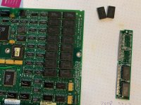
HA! Sometimes you have to get lucky... found that some LC VRAM SIMMs used the same 256Kx4 VRAM chips.

First two chips replaced:

IMG_1781.jpg

Line is GONE. :D

Card is fixed.

Curious what happens when I put the two spare chips onto the LC SIMM


Von

Well-known member
So the problem you just fixed was with a Micron Xceed card card have a line on screen when used in conjunction of a grayscale adapter?

I have 2 Xceed cards and one of them has the line...

 
Last edited by a moderator:

joethezombie

Well-known member
Just wow.   :-O  Incredible work.  And of course, micron memory going bad again.  Always the MT crap going bad in the original 128Ks and even my Iic.


Bolle

Well-known member
So the problem you just fixed was with a Micron Xceed card card have a line on screen when used in conjunction of a grayscale adapter?
The line was also there on an external screen.

Actually the card I got here is the exact card that started this thread.


Bolle

Well-known member
Just got another one of those cards onto my workbench.

Similar symptoms, just 4 vertical lines (in B/W mode at least) this time showing random junk:

IMG_3299 2.jpg

Turns out the chip in the exact same location as on the card @JDW sent me was bad along with another one that was just starting to produce bad pixels here and there:

WhatsApp Image 2020-06-09 at 18.05.33.jpeg

I wonder what's causing the same single chip out of 16 to fail on two different cards?

Is it possible that chip failure can be caused by static from the anode? Because this is the chip closest to the anode when installed in the machine.


trag

Well-known member
I wonder what's causing the same single chip out of 16 to fail on two different cards?

Is it possible that chip failure can be caused by static from the anode? Because this is the chip closest to the anode when installed in the machine.


Interesting.   I can't think of a good way to test it though.   You could try shielding the chip in question, but how many years does it take to generate a failure, and how many cards would you have to test with both unshielded and shielded to get meaningful data?


JDW

Well-known member
[SIZE=1.4rem]...4 vertical lines (in B/W mode at least) this time showing random junk...[/SIZE][SIZE=1.4rem] the chip in the exact same location as on the card [/SIZE]@JDW[SIZE=1.4rem] sent me was bad along with another one that was just starting to produce bad pixels here and there...[/SIZE]  I wonder what's causing the same single chip out of 16 to fail on two different cards?
I'd love to have a schematic of those video cards to find out!  The company who made it is long gone, but it would be nice of the IP owners or engineers at the time could donate technical documents to the vintage Mac community.  Rebuilding the schematic isn't impossible, but it takes more time than any of us care to invest.

 
Top