• Updated 2023-07-12: Hello, Guest! Welcome back, and be sure to check out this follow-up post about our outage a week or so ago.

SE/30 Motherboard: UB10 & UB11 SONY Sound Chip Voltages

JDW

Well-known member
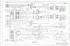
Have any of you ever measured voltages at UB10 or UB11 (Sony chips) on an SE/30 motherboard?  I don't have a long enough cable to safely pull out the motherboard to test that.  I am specifically curious if capacitors C3, C4 & C5 see a maximum of 5V or 12V.  I suspect one or more of those 3 capacitors do see 12V since the SE/30 schematic shows 12V going into those SONY chips at more than one location.  A datasheet on those SONY chips would be wonderful, but I can't find anything like that.
SE30_P7.GIF

The reason I ask about the voltages across C3, C4 & C5 is because I've been re-evaluating the tantalum capacitors everyone uses to recap SE/30 boards.  Not everyone uses tantalum, but those who do, even Console5 tantalum cap kits, all use 47uF 16V rated caps.  Whoever started that trend either didn't know about derating SOLID tantalum caps or they ignored that due to the fact the appropriately rated 25V 47uF solid Tantalum caps wouldn't fit the pads. 

I know for a fact C9 & C10 do see 12V constantly. It's also a fact that Solid tantalum must be 50% derated. A 16V rated tantalum cap should never be used where the voltage is higher than 8V in its steady state condition, otherwise its failure probability will increase.  This isn't speculation. It's on the datasheets. And with solid tantalums, the failure mode is a short circuit and a flame.  That failure mode doesn't mean tantalum should never be used.  It merely means tantalum must be used intelligently, with manufacturer recommendations properly understood and implemented. Indeed, there are tantalums used in military, space and medical applications (yes, even pacemakers) that can be used at their full rated voltage, but those are priced outside what most consumers can afford.

The good news is that polymer tantalums have only a 20% derating requirement, which means a 16V polymer tantalum can take 12.8V constantly and not have major reliability issues as per manufacturer datasheets.  

I know C1, C7, C8, C12 & C13 only see 5V, so folks who have used solid tantalum 47uF 16V Solid Tantalum caps there are abiding by manufacturer specifications -- no problems with those.  C9 & C10 are definitely out of spec though if 16V Solid Tantalum is used.  

Again, I am curious to know if C3, C4 & C5 are out of spec too.  If you've ever measured 12V at C3, C4, or C5, please let me know.

Thank you!


aeberbach

Well-known member
My SE/30 board is living in an external development setup right now. I was able to measure 5V on C3, C4, and C5.


aeberbach

Well-known member
With the scope on the capacitors I see peaks at 12V, such as when pressing S2 (ascending tones). I haven't got a system installed that can play a continuous sound right now I'm afraid. 5V is the baseline.


JDW

Well-known member
With the scope on the capacitors I see peaks at 12V, such as when pressing S2 (ascending tones). I haven't got a system installed that can play a continuous sound right now I'm afraid. 5V is the baseline.


Thank you for confirming on a scope that you see 12V peaks on each of those 3 capacitors.  That's what I was afraid of. Transient peaks or not, anything above 8V is technically over-voltage regarding 16V Solid Tantalum capacitors which have a strict 50% derating requirement.  The likelihood of failure increases significantly when voltages rise above that derating value.

All said, the following 5 capacitors (on SE/30 motherboards) need to be Polymer Tantalum versions (if using Tantalum replacements) in order to abide by datasheet guidelines and also fit the pads.  Again, those guidelines are there to ensure the caps won't go up in flames due to over-voltage:

C3

C4

C5

C9

C10

The other five 47uF caps on that motherboard are hit with only 5V so it's fine to use a 16V solid tantalum cap there.

Anyway, you answered my question perfectly, @aeberbach.  A thousand thanks for your very kind help in performing that testing!


ttb

Well-known member
I recapped my SE/30s with all polymer tantalum caps and I haven't run into any issues so far. The added cost was negligible. Good to know there was perhaps a real reason for me to do that :)  


JDW

Well-known member
I recapped my SE/30s with all polymer tantalum caps and I haven't run into any issues so far. The added cost was negligible. Good to know there was perhaps a real reason for me to do that :)  


That's great to hear.  I have selected some polymer caps already, but if you don't mind sharing what caps you chose, that would be helpful.  I am especially curious about ESR.  For most of the caps, low ESR is good, but I was wondering how it would affect the audio, since two of those caps have series resistors attached.  Is loudness the same, better or worse, post-recap?


keropi6k6

Member
Hello!

I recently got a SE/30 as well and in the interested of making it last several more decades I started fully recapping it.

I do not understand the trend of replacing electrolytic capacitors with tantalum ones, I see this on amiga world as well...

Anyways I am about to order these organic polymer caps for the logic board, Panasonic ZA series: https://gr.mouser.com/ProductDetail/667-EEH-ZA1E470V

sadly there is no 1uf value made so I will put this one for the single capacitor of this type on the motherboard : https://gr.mouser.com/ProductDetail/667-EEE-HD1H1R0R

Any objections to the above?

thanks!


JDW

Well-known member
No "objections" but I do have "reservations." :)

You have chosen HYBRID Polymer Aluminum capacitors (47uF).  Those are superior to the regular (stock) Aluminum Electrolytic capacitors in terms of low ESR, and in terms of "leakage current" they are superior to SOLID Polymer Aluminum capacitors (and SOLID polymer tantalum too).  But the SOLID electrolyte Aluminum capacitors are superior to the HYBRIDs you have chosen in that the SOLID electrolyte cannot "leak" out of the capacitor over time. The higher leakage current of the SOLID version caps won't matter on the SE/30 motherboard for 8 of those 47uF caps. Only C3 & C4 used on the SONY sound chips MIGHT have issues with replacement caps that have higher leakage current.  I doubt it, but that is why I await word back from @ttb regarding any differences in sound after his polymer tantalum recap.  Even so, the leakage current of polymer Tantalum (75.2uA) is lower than the leakage current of SOLID polymer Aluminum (400uA) like these: https://www.mouser.jp/ProductDetail/Wurth-Elektronik/875105344006?qs=0KOYDY2FL29piTbBKO%2B6mw%3D%3D

The reason people recap is because they are mainly replacing older electrolytic capacitors which have a liquid electrolyte that can leak out over time. Leaked fluid left on the board a long time can eat through PCB traces.  It can be hard to detect where those breaks are too.

So if you replace with HYBRID Polymer Aluminum capacitors, that fluid electrolyte can, in theory, leak just like the standard Aluminum types, given enough years (say 15 years or so, depending on usage and heat).

So in my mind, the two best types of replacement capacitors for the SE/30 motherboard would be either:

Polymer Tantalum  (has a solid electrolyte)

or

SOLID Polymer Aluminum (the "can/wound" types look like the stock capacitors, but have higher leakage current than Polymer Tantalum)

SOLID Polymer Tantalum capacitors have a 20% voltage derating which means a 16V Polymer Tantalum 47uF capacitor for the SE/30 motherboard could handle 16V x 0.8 - 12.8V continuously without compromising its failure rate.  This is in accordance with manufacturer datasheet recommendations.  And 16V Polymer Tantalum capacitors will fit the pads of the SE/30 motherboard without problem.  So my personal pick for the 47uF caps would be these:

https://www.mouser.jp/ProductDetail/AVX/TCJY476M016R0070?qs=sGAEpiMZZMtlaK70QcheAidQ2H%2BGPldiGPIdMja3KYo%3D

And you can get the same type of polymer cap to replace the stock 1uF too.  Just make sure you choose a 1uF replacement cap whose body will fit the pads on the motherboard.

 
Last edited by a moderator:

keropi6k6

Member
Oh I see, thanks for the insight

I was under the impression the ZA ones would not leak... good to know!

Allright I am now not sure if I go witht the "can" shaped ones  or the tantalums LOL  :)  

price-wise the canned are cheaper:

jmfeuTgl.png


I can't imagine leakage is that huge of a deal - I assume the original 1989 caps would be worse in that aspect?

In the meantime this 25v 1uf one will be fine for the sinlge cap of this value, right? It cannot be avoided to use this type I think...

https://gr.mouser.com/ProductDetail/AVX/TCJP105M025R0500E?qs=%2Fha2pyFadujLdpNRQGKrUQvk6tlHy%252Bh4Yoo5VnKyKahn7piaPbIIUJ3bRbC%252By0pa

Luckily the system was in working and very good cosmetic condition, there was some fuzziness in the audio caps area and some at the power connector but nothing as bad as damaged traces or pads.

2latyjwl.jpg


It will be a couple of days before I place my mouser order so I hope during the weekend @ttb can chime in.

Appreciate the help @JDW , thanks!!!!!


JDW

Well-known member
I can't imagine leakage is that huge of a deal - I assume the original 1989 caps would be worse in that aspect?

In the meantime this 25v 1uf one will be fine for the sinlge cap of this value, right? It cannot be avoided to use this type I think...

https://gr.mouser.com/ProductDetail/AVX/TCJP105M025R0500E?qs=%2Fha2pyFadujLdpNRQGKrUQvk6tlHy%2Bh4Yoo5VnKyKahn7piaPbIIUJ3bRbC%2By0pa


It's important to keep the terms straight.  "Leakage Current" is totally different than "leaked fluid."  You probably understand that already, but I just want to be 100% clear.  The 1989 stock caps leak fluid, and they also have very low leakage current.  Why so low?  Because all fluid filled aluminum electrolytic capacitors (NOT polymer) have low leakage around 6uA or less (in terms of the 47uF caps we're talking about). The HYBRID fluid-filled Polymer caps have the same tiny leakage current too; but as I said previously, the disadvantage to ANY fluid-filled cap (including HYBRID Aluminum polymer) is that fluid will eventually leak out.  (Again, "leak out" doesn't mean "leakage current.")

8 of the 10 47uF caps won't matter when it comes to leakage current.  I cannot say anything about C3 & C4 though because those caps have a series resistor and are part of the audio circuit, so again, I await @ttb on that.  But I don't think it will be an issue.

As to that 25V 1uF SOLID Polymer Tantalum cap you linked, it's Length = 2mm, which might be too tiny to fit the pads.  I'd suggest going with a 50V 1uF cap because it's Length of 3.5mm will definitely fit the pads on the SE/30 motherboard:

https://www.mouser.jp/ProductDetail/KEMET/T521B105M050ATE200?qs=AQlKX63v8RsV9oAZX%2FN9fA%3D%3D

This 1uF 50V AVX part will work too, but it's more expensive:

https://www.mouser.jp/ProductDetail/AVX/TCJB105M050R0300?qs=jDaUAV6rIX9RuRuJdZsOKg%3D%3D

 
Last edited by a moderator:

keropi6k6

Member
Indeed I was talking about "leakage current" 

Once again some good info, I will go with the can capacitors and the KEMET 1uf one  ::)

now for the final piece of the puzzle - tbh I don't think it will even matter in the end


ttb

Well-known member
This is the cart I use whenever I order a set of SE/30 logic board caps: https://www.digikey.com/short/z134vr The specific part is this: T521V476M020ATE090 KEMET | Capacitors | DigiKey

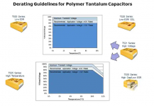
I'm using KEMET 20V poly tant caps for all of the 47 uF parts. Nominally its a "low ESR" part with a 90mOhm ESR at 100kHz. KEMET specifies a 20% derating for specified voltages over 10 V, which these are. That means 16 V which would still give some headroom per @JDW's concern and @aeberbach's measurement. Note that they allow for no derating for transients, as well. 

image.png

I didn't notice any difference in volume, but I will set up a test (e.g. play a sine tone and measure the waveform at he speaker port) and report back with the test conditions and result so you guys can compare. I think I have a board with regular tantalum capacitors on it I'll compare as well.

 
Last edited by a moderator:

JDW

Well-known member
I think I have a board with regular [solid] tantalum capacitors on it I'll compare as well.


That comparison is welcomed because solid tantalums will have an ESR ranging from 0.7 to 1.1 ohm, depending on part number, which is much higher ESR than the polymer tantalums.


ttb

Well-known member
Alright, I haven't done both SE/30s yet as my solid tantalum system is awaiting a new HD right now, but here are some preliminary results and methodology so you guys can hopefully compare. 

Test method:

  1. I generated a 1kHz sine tone with Sound Edit 16. It's 10 seconds long and has an 80% amplitude. I saved this as a System 7 sound, attached to this post (stuffed with Stuffit 1.5).
  2. I set the system volume to maximum.
  3. I connected a Hosa 3.5mm TRS to 2x 1/4" TS adapter cable to the computer's audio output port. 
  4. I connected a multimeter to the left channel's TS plug with large alligator clips. You could use an oscilloscope, but I wanted this test to be as accessible as possible.
  5. The multimeter was set to AC mode, auto range.
  6. The sound file is played by double-clicking it and the RMS voltage is read on the multimeter.

Results:

  1. Mystic CC with solid tantalum caps (baseline, included just because I made the sound file on it): 0.278 Vrms output
  2. SE/30 with polymer tantalum caps (running A/UX 3.1, but that shouldn't matter): 0.449 Vrms output

Discussion:

  1. This test is from the phone jack which is after the caps in question but still omits part of the circuit (including a few caps) that feed the speaker. Ideally the measurements would be taken both at the speaker jack and at the phone jack.
  2. This test is performed into a high Z load (10 Mohm), so there will be very little current involved. This means the results may not match reality unless you are running from the phone jack into a high Z input.
  3. Perhaps the most fair would be to test multiple boards with the same load (e.g. speaker), measuring voltage at the load itself.


Thoughts? Anecdotally the SE/30 is significantly louder through the same headphones compared to the CC, so I believe these results match reality in that respect.

View attachment 1kHz 80pct 10s.sit


JDW

Well-known member
@ttb

Thank you for the time you invested in all of that testing. You did far more than I thought you would.

What I thought you were going to do was test your solid tantalum motherboard and then test your polymer tantalum motherboard in the same machine (one at a time, obviously) using the same speaker, max out the volume, and let your ear decide which motherboard is louder, or see if both are about the same volume, roughly.

The CC data is interesting, but it’s a totally different motherboard, so that data difference could very well be normal.

All said, I am mainly curious to see if the lower ESR of polymer tantalum caps on the SE/30 motherboard affects the sound quality or volume as compared with higher ESR solid tantalum caps.


ttb

Well-known member
Absolutely, I plan on measuring my other board this week when I have time to do the swap. The purpose of the test above was to provide a way for anyone to compare sound output levels objectively. I'm also concerned that the difference between polymer and solid tantalum caps will be so small that it won't be audible.

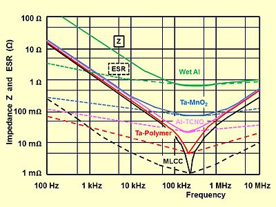
Also, note that although the ESR of the polymer caps is much lower, the impedance is not that much different in the audio frequencies, at least according to this chart: 

iu


I'll leave it to an actual electrical engineer to opine on whether that matters.


JDW

Well-known member
...the impedance is not that much different in the audio frequencies, at least according to this chart: 


I'll leave it to an actual electrical engineer to opine on whether that matters.


Compared to the stock "Wet Al" (Aluminum Electrolytic) capacitors, the impedance (Z) and ESR of both SOLID Tantalum (Ta-MnO2) and Polymer Tantalum (Ta-Polymer) is much lower at all frequencies. 

Because there is no datasheet on the UB11 & UB10 sound chips and because I cannot pull my own SE/30 motherboard out far enough to probe it, I have no idea what kind of signals (e.g., 5V 0v-peak square wave? 12V peak-to-peak sine wave? DC offset on a sine wave?) are present on pin-10 of those chips, which in turn feed 47uF capacitors C3 & C4.  But I decided to make some assumptions and run a simulation...

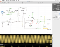
Using the schematic in my opening post as a guide, I reconstructed the audio part of the circuit in iCircuit, as shown in the following screenshot: 

Simulation.png

I accounted for leakage and ESR of capacitors C3 & C4, but I did not account for capacitor ESL (inductance).  The ESR is shown in your graph by the dashed lines.  Also note that I have no idea what the value of L2 is, so I took a wild guess that it is 33uH.  I tested different inductance values at L2, but that did not affect anything that I could see on the simulated output to the speaker.

I tested a 1kHz waveform with a 6V amplitude and no DC offset.  The left and right channel amplitudes add to the total amplitude at the speaker output.  As you can see, it's 10.98V peak-to-peak at the speaker output in this condition, assuming a Polymer Tantalum ESR of 40m-ohm at the 1kHz frequency, which is realistic.  

With an aluminum electrolytic capacitor (like the stock caps), you have something close to about 2-ohms ESR but only 3uA leakage current.

All said, the peak-to-peak output at the speaker in this simulation is 100mV higher with the low-ESR Polymer capacitors.  That increase in output isn't much and probably could not be heard if you tried to compare.  I could not see any change at the output with a higher or lower leakage current value, which suggests that the higher leakage current of tantalum capacitors (as compared with aluminum electrolytic caps) won't matter here.

It seems clear that a 16V or 20V 47uF Polymer Tantalum recap of the SE/30 motherboard is safe and will not have a noticeable impact on the audio circuit.  And the impact of low ESR is a small increase in the output speaker volume.

And last but not least, I separately simulated the MacEffects Clear Speaker, which is .  The peak-to-peak output at the Speaker dropped from 10.98v (with 63Ω speaker) to 3.59v (with 8Ω speaker), apparently because this circuit simply cannot supply the current necessary to drive such a small load.

 
Top