I'm actually planning on assembling some kits / rominators since it's open source now, so this is kinda well timed, though I'm sorry you're having issues.
I'll be building one for a Plus, as soon as the PCB's from JLCPCB get here hopefully in 1-2 weeks, as time allows.
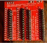
The secondary reason I bring up pins/sockets... the DIP IC's going on the Rominator can go into "double wipe" or machined pin sockets. that to me difference isn't a big deal, though machined is less forgiving on installation and harder to remove IMHO. But if I understand installation correctly, there are then pins sticking downward from the Rominator to mate into the logic board. These could theoretically be machined pin headers, standard .100 jumper style pin headers, or in a perfect world, something like these:
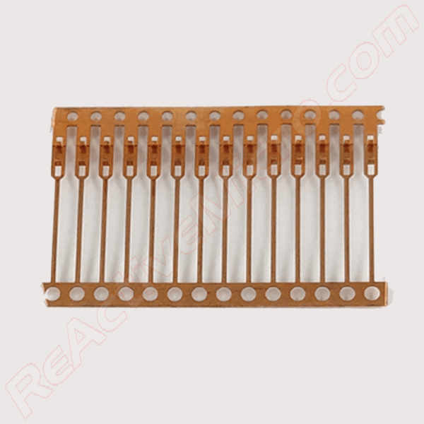
These are lead frame pins, which are edge mounted on a standard 64mil / 1.6mm thick PCB. Pitch is 100mil / 2.54mm spacing. Thickness is 10mil / .25mm. They allow mating with DIP sockets without causin

www.reactivemicro.com
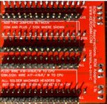
Round or square header pins have been used in the past to create a PCB with IC legs. However these unfortunately all damage dual-wipe sockets once mated. And once removed, an IC is no longer able to be installed in the socket and provide reliable contact. In contrast, the lead frame pins are designed for this application and do not damage sockets in any way.
Those pins are more expensive, but technically, the right ones for the job. The rominator kits I have seen previously used round or square pins which could damage the sockets on the Mac itself.
")