• Updated 2023-07-12: Hello, Guest! Welcome back, and be sure to check out this follow-up post about our outage a week or so ago.

Reverse Engineering the Macintosh SE PCB & Custom Chips for 1:1 reproduction

Kai Robinson

Well-known member
Hmm, i've redone some of the traces around the SND/Serial SCC stuff - i discovered that the 26LS32 is not correctly connected! There's a tiny trace that goes from Pin 1 (1B inverting input) to a via, and i missed that - having that unconnected could be throwing off stuff...it's a longshot, but i can try...i'm basically going over every via/trace on the sprint layout, ensure that nothing is unconnected - plus lining stuff up a little better - has no effect on the signalling, but I like things to be as neat as possible :D

 
Last edited by a moderator:

maceffects

Well-known member
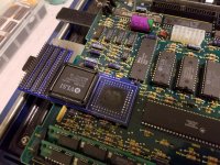
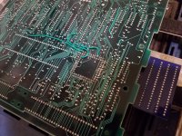
Some good news, despite my failures of desoldering (lesson learned), @ymk assisted me in repairing the issues with the board and correcting the breakout issues.  Now, we have a fully functional board with breakout.  @ScutBoy was kind enough to lend his Brainstorm system (don't worry I used my own logic board) so I'll be sending that to @asicsolutions.  He is very busy wrapping up the Micron Xceed project so I wouldn't expect results for quite some time.  If/when I have an update I'll post it.  

20210129_233419.jpg

20210129_233435.jpg


quorten

Well-known member
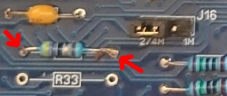
Mentioning bodge wire and unconnected traces that shouldn't affect signaling... well that's one thing that old and slow computers are quite a bit more forgiving on!  If I've read the schematics correctly, though, the Macintosh SE does in fact use some impedance-matching resistors for certain high frequency signals like the clock lines, RAM RAS, RAM CAS, and RAM WE... so that could be a hint to scrutinize the quality on those lines.

@Kai Robinson Alright, I think I have another thought looking at the board photos in detail.  I noticed R33A, yes a 47 ohm impedance-matching resistor on a RAM CAS line, might have a soldering quality issue.

board_inspect.jpg

 
Last edited by a moderator:

maceffects

Well-known member
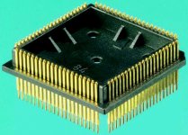
I just discovered male PLCC 84 adapters that might have saved a fair bit of trouble. Those could be good for building a PCB in the future though. 
 

Does anyone know a “cheap” logic analyzer that has at least 84 channels and that a novice like me can capture/store data and sent to someone more qualified? This could save a fair bit of trouble.

C862427B-D3C1-4ADC-AAE5-17B3A781E0A6.jpeg


Scott Squires

Well-known member
Check your local craigslist for vintage HP logic analyzers. For example, last month on my local craigslist there was an HP 1660B (136 channels) for $100, though only had enough probes for 68 channels. You can find additional 34 channel probes on eBay for $30 or so. Currently there is an HP 1651B (102 channels) with a full set of probes for $120. These are '90s professional logic analyzers. They have 250 MHz timing speed and 100 MHz state speed, which make them extremely capable for retro applications.

HP 16x0 analyzers have 136 channels, 16x1 have 102, 16x2 have 68, and 16x3 have 34. The 'x' is the generation. The entire series had the same performance specs (250 MHz), basically over time they added more convenience features, more memory depth, etc.

You might also see Tektronix logic analyzers which would be suitable, but I don't know what models to look for from Tektronix.

 
Last edited by a moderator:

Scott Squires

Well-known member
There are also the HP 16500 and 16700 series that you might come across. They are much larger and use an expansion card system for all logic and scope functions, so you have to check which cards it comes with.


Kai Robinson

Well-known member
Mentioning bodge wire and unconnected traces that shouldn't affect signaling... well that's one thing that old and slow computers are quite a bit more forgiving on!  If I've read the schematics correctly, though, the Macintosh SE does in fact use some impedance-matching resistors for certain high frequency signals like the clock lines, RAM RAS, RAM CAS, and RAM WE... so that could be a hint to scrutinize the quality on those lines.

@Kai Robinson Alright, I think I have another thought looking at the board photos in detail.  I noticed R33A, yes a 47 ohm impedance-matching resistor on a RAM CAS line, might have a soldering quality issue.

View attachment 40288
Ooh, good catch, i'll check that. 


cheesestraws

Well-known member
What errata are between this and the board you sent me (1.4something?)?  The short at the PDS card slot (where is best to cut that?) and the missing 26LS32 connection?


timdorez

Member
I think there's a mistake in the Bomarc SE schematics.

Pin 2 & 4 of the SND chip are respectively linked to pin 4 & 2 of the VIA chip in the Bomarc schematics but I found out they aren't swapped and pin 2 of the SND chip goes to pin 2 of the VIA chip and same for pin 4.

Hope it is useful for those checking @Kai Robinson's board using the schematics. :)  


Kai Robinson

Well-known member
Just a quick one - we can eliminate another annoying to find IC from the list - the MC3488 (Dual Line Driver) can be replaced with the SN75150, which makes sense since later machines use the SN75175 Quad Differential Driver. Pinout is identical, function is identical. Best thing is they're only £1.36 a piece from Mouser Electronics. 

I've busted out my IC tester to re-verify the 74F257's and 74LS245's - they check out fine. I've gone over the board again, and bodge wires are a thing, still, just double and triple checking that everything is connected where it should be.


Scott Squires

Well-known member
I don't think Hackaday pretends to be traditional journalism. The internet is going to internet. It will make more people aware of your project and that's a good thing.

 
Top