• Updated 2023-07-12: Hello, Guest! Welcome back, and be sure to check out this follow-up post about our outage a week or so ago.

Reverse Engineering the Macintosh SE PCB & Custom Chips for 1:1 reproduction

maceffects

Well-known member
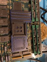
I’ve soldered together the breakout board it was quite tedious and I put a bit too much solder in the extension pins as I couldn’t get them to stay very well. I know everything looks like a very amateurish job but it works. I could have slowed things down to look better but had limited time. 
 

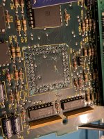
Unfortunately, I couldn’t clear out all the PLCC pins and solder on the logic board. I was starting to damage the board with heat so I gave up for now. Despite having a Hakko desoldering gun, it was an unpleasant process. 
562B7583-201C-4D92-9DD4-01F9ED02C04B.jpeg

8539E499-7869-4319-8B7E-EA1572D36FEE.jpeg


Kai Robinson

Well-known member
@maceffects did you flood the socket area with flux? You need a temp of around 420 degrees centigrade on a desoldering gun.

To remove cleanly, you need to add fresh solder to the pins or holes left behind, you NEED flux so it flows nicely, then it's a matter of using the desoldering gun on the pads. Max of a second on the pad, tip flat, not at an angle, then wiggle a little then press the trigger.

Right now, I'd advise re adding solder to the socket area and continuity test, patch any broken traces later. 


nyankat

Member
Definitely add fresh flux and solder, but instead of a desoldering gun, try a good copper braid instead. It'll still suck the solder out, but scratch up the traces less.


maceffects

Well-known member
Thanks everyone for the tips, normally my Hakko de-soldering gun solves all my problems but this thing is stubborn. I didn’t use flux, fresh solder, and I only had the gun at around 375c. I did have it on for 2 seconds and wiggle, but no dice. I tried cutting the plastic off up top to see if things could be desoldered on that side (hence the cosmetic scratches). I’ll be experimenting next weekend to see what I can get done. Hopefully I didn’t damage traces such that they can’t be used because I don’t have the experience to repair that. 


Bolle

Well-known member
Pre-heat the area with hot air set to around 200°C. Works very well for me and I never have to use additional solder or even flux to get things cleanly off any board.


Phipli

Well-known member
@timdorez

You'd probably want to be checking for shorts as well as continuity - which would be quite time consuming, but if you did we'd find anything.

Also at some point we might have issues with chip timings - sometimes chips of different grades or even just from different manufacturers don't work in a circuit because they're too slow / too fast. Best to start with as many reappropriated chips to start as long as they don't get damaged.

On that subject - @Kai Robinson do you have one of these (random listing, shop around)? If not, get one!

https://www.ebay.co.uk/itm/New-IC-Tester-74-40-45-Series-lC-Logic-Gate-Tester-Digital-Meter-/271634652740

Also, these are useful :

https://www.ebay.co.uk/itm/LCR-TC1-Transistor-Tester-ESR-Capacitance-Meter-Electronic-Component-NPN-PNP-/353176611089?

Available from UK sellers too.

 
Last edited by a moderator:

cheesestraws

Well-known member
On that subject - @Kai Robinson do you have one of these (random listing, shop around)? If not, get one!


Also worth noting that if one has a TL866 II programmer, which seem to be rather widespread, it has a logic chip test mode in it as well, which has worked better than I was expecting when I've used it, anyway.


Phipli

Well-known member
Also worth noting that if one has a TL866 II programmer, which seem to be rather widespread, it has a logic chip test mode in it as well, which has worked better than I was expecting when I've used it, anyway.
Fair point - I have both and got the tester first. Still handy as it doesn't need a computer, but not worth purchasing if you have an TL866.


cheesestraws

Well-known member
Fair point - I have both and got the tester first. Still handy as it doesn't need a computer, but not worth purchasing if you have an TL866.


Yup.  More that I didn't find the logic tester feature until some considerable time after I had bought the programmer, so wanted to flag it up in case anyone else is as oblivious as I am :) .

 
Last edited by a moderator:

Kai Robinson

Well-known member
Awesome ! Where did you find that ?

So, in theory, verifying the components one by one using the Bomarc schematics would be enough to find the issues with your board, right ?

If you can forward me a board, that's definitely something I can do ! ;)


Thanks to Johan Grip on the Retro Tinkering discord - he located them here: https://www.macintoshrepository.org/28274-mac-se-schematics

Would you like a blank board to build up?


Kai Robinson

Well-known member
@quorten just looked through Mac Repository - the Bomarc schematics of the 128/512k and the Plus are on there, too - were uploaded last year - i remember you were after some better ones :)


quorten

Well-known member
I'd guess probably the most useful thing from @timdorez's tech manuals is the troubleshooting info, seems like the other schematics are largely the same as what currently floating around but always worth taking a more detailed look!

Nice find on the Bomarc Macintosh SE schematic... macintoshrepository.org is a pain to deal with and yeah it's understood that the Bomarc schematics didn't make it out to public on good terms, but... well, it's info that can be digested into a schematic redraw under better terms, in a different style and format.  I'll probably get around to doing full schematic redraws in the KiCad style similar to the SE/30, but for all of the SE, Plus, and 128k/512k.

But what's somewhat a bummer about this... sure you can create the ideal knowledge repository, but as most of our community primarily interacts via search engines, it won't make it out to search engine results until years later.  Well, no hurry on that I guess.


DrewNucci

New member
I'd guess probably the most useful thing from @timdorez's tech manuals is the troubleshooting info, seems like the other schematics are largely the same as what currently floating around but always worth taking a more detailed look!

Nice find on the Bomarc Macintosh SE schematic... macintoshrepository.org is a pain to deal with and yeah it's understood that the Bomarc schematics didn't make it out to public on good terms, but... well, it's info that can be digested into a schematic redraw under better terms, in a different style and format.  I'll probably get around to doing full schematic redraws in the KiCad style similar to the SE/30, but for all of the SE, Plus, and 128k/512k.

But what's somewhat a bummer about this... sure you can create the ideal knowledge repository, but as most of our community primarily interacts via search engines, it won't make it out to search engine results until years later.  Well, no hurry on that I guess.
how is progress with revamped boards? Were you able to fix all the traces and get a proper 1:1 repro yet? Btw I noticed with one of the pictures that was uploaded where some traces went to vias where they should have just been straight traces, there was one section that was circled that needed to be fixed where the trace to the left of it had a similar problem, but I’m not sure if you noticed it or not. 

if there is some way I can help such as comparing high res photos or the repro boards and the original to ensure the traces are correct and there are no connected vias where there shouldn’t be any, I’m happy to give it a look and be another set of eyes to ensure faithful reproduction of these boards. 
 

I am extremely excited for the SE/30 version to be done eventually. The SE/30 is my dream computer. I’m rocking a Mac classic I repaired and brought back from the dead. (I even was able to get a modern scsi/3 15k rpm server drive to work on the 50-pin stock scsi bus to work on the Mac classic. I have some other issues with the comp though. I think the external scsi port and the serial port/chip has some issues which causes the computer to crash if an external scsi drive or the AppleTalk plugs are plugged into the back of the machine along with an audio issue I can’t seem to resolve. I have no audio at all on the computer and I think it’s due to the battery that destroyed part of the board. 
 

id love to start making and selling rascsi HD’s with raspi zeros to help people replace HD’s instead of the 15k server hd I used. Plus the scsi2sd is too expensive of a replacement for these comps. If I can make a rascsci affordable (around 20$) I think it’ll go a long way to help preserve these beautiful machines. I think many people who get these comps to refurb them don’t realize how much of a pain getting replacement HD’s can be. Anyway I’ve drones on enough. Let me now how I can be of service and make this project gain any more progress. Thanks.


Kai Robinson

Well-known member
how is progress with revamped boards? Were you able to fix all the traces and get a proper 1:1 repro yet? Btw I noticed with one of the pictures that was uploaded where some traces went to vias where they should have just been straight traces, there was one section that was circled that needed to be fixed where the trace to the left of it had a similar problem, but I’m not sure if you noticed it or not. 

if there is some way I can help such as comparing high res photos or the repro boards and the original to ensure the traces are correct and there are no connected vias where there shouldn’t be any, I’m happy to give it a look and be another set of eyes to ensure faithful reproduction of these boards. 
 

I am extremely excited for the SE/30 version to be done eventually. The SE/30 is my dream computer. I’m rocking a Mac classic I repaired and brought back from the dead. (I even was able to get a modern scsi/3 15k rpm server drive to work on the 50-pin stock scsi bus to work on the Mac classic. I have some other issues with the comp though. I think the external scsi port and the serial port/chip has some issues which causes the computer to crash if an external scsi drive or the AppleTalk plugs are plugged into the back of the machine along with an audio issue I can’t seem to resolve. I have no audio at all on the computer and I think it’s due to the battery that destroyed part of the board. 
 

id love to start making and selling rascsi HD’s with raspi zeros to help people replace HD’s instead of the 15k server hd I used. Plus the scsi2sd is too expensive of a replacement for these comps. If I can make a rascsci affordable (around 20$) I think it’ll go a long way to help preserve these beautiful machines. I think many people who get these comps to refurb them don’t realize how much of a pain getting replacement HD’s can be. Anyway I’ve drones on enough. Let me now how I can be of service and make this project gain any more progress. Thanks.


Tomorrow is the day of hopefully more progress - today has been a day to just relax after the tough week i've had! I've got some multicoloured solid core wire to hook up to the board in various places for ease of monitoring signals - i really really want a DIP64 test clip for my logic analyzer!

I'll post the updated Sprint file in a sec actually, the image files were already shared a page or two prior. 

Which traces went to via's btw? If you've noticed them i'll compare them to the sprint layout. 

View attachment MacintoshSE.lay6

 
Top