• Updated 2023-07-12: Hello, Guest! Welcome back, and be sure to check out this follow-up post about our outage a week or so ago.

Repairing traces on a derelict Mac SE/30 board / questions

krishnadraws

Well-known member
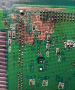
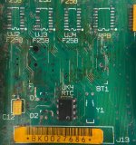
First time doing this (and first time working on a Mac SE/30). Attached is the area I'm fixing. There was a lot of corrosion on the board due to an exploded Maxell battery. I've gotten it to a point where it's looking decent. Broken traces are definitely there. My question is: What do I do with the vias? Do I solder them on the other side of the board? I'm referring to the vias below UJ2F258 and the ones that span horizontally to the right from that point. (see photo) 

I've also included the underside of the board, which is looking pretty rough. 

Any advice or feedback on precautions / best practices for this, particularly from those who have already undertaken such a task, would be greatly appreciated. I've got new F258's, D1, D2, Y1 and RP8's on order and they should arrive this weekend. New battery and 1/2AA battery holder are already here but I can't put those in until I fix all the traces. Also, above BT1 there is a notch where I believe the battery holder peg sits inside. Currently, it's blocked - do I simply drill it out? 

Thanks a bunch!
Screen Shot 2020-02-11 at 4.51.48 PM.jpg

Screen Shot 2020-02-11 at 4.59.00 PM.jpg


LaPorta

Well-known member
I can offer a few suggestions based

on my limited experience.

1: Your diodes D1 and D2 need to be replaced before your date and time will work (these are in series with the RTC circuit). I’m not sure if that is crud on the pads for them, or if the pads are totally eaten away.

2: First, I’d try a good blob of flux on top of that battery box post, heat it with your iron, and try to push down on it with the iron. I’ve been able to push it through the other side far enough that you can quickly yank it out with pliers before the pliers sink all of the heat out of the solder.

3: A LOT of those pins will need to be cleaned up and resoldered on the back of the board. As far as the non-conductive coating eaten away, the copper still looks to be in good shape. I’d say once everything is fixed and complete, use something like liquid electrical tape to coat all those surfaces. You don’t want any shorts there.

4: I’ve got two SE/30 boards, and I can certainly get photos of the same area for you.

 
Last edited by a moderator:

Bolle

Well-known member
Those vias don't look fixable. Most of the vias in that are do not go from top to bottom layer but to one of the inner layers.

Your only chance is finding out which via was what signal and run a whole new wire for that.

You will end up with a lot of wires between the ROM SIMM (looks like you have to replace that too), CPU, PDS socket and the RAM address muxes.

I did this once on a board that didn't look as bad and ended up with 20 patch wires.

Counting dead looking vias alone on the pictures I would say you will have to run at least 50 wires.

Start with hooking up all signals between ROM and CPU. You want at least a death chime before you start to worry about wiring the RAM address muxes back in.

Once that works and you don't get a death chime anymore go for the easy stuff and rewire the RTC.


krishnadraws

Well-known member
Thanks! Is there any place to source the ROM socket? Also, if the vias are toast, is it even worth attempting to fix this board?

I’ve already put a little money into recapping the board (95% complete). But 50 trace fixes seems somewhat daunting given the small real estate I have to work with. 

One of the diodes has all of its pads gone. I’ll give the solder gun “poke” method a try. 


Top