• Updated 2023-07-12: Hello, Guest! Welcome back, and be sure to check out this follow-up post about our outage a week or so ago.

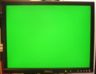
Radius TPD/SE up and running . . . on an LCD no less!

Trash80toHP_Mini

NIGHT STALKER
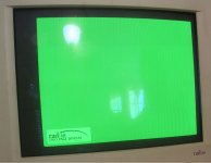
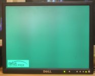
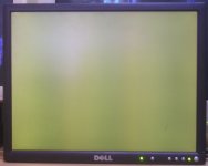
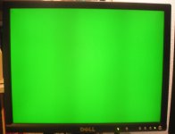
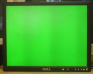
Radius-TPD-SE-GREEN-LCD.JPG

Still need to get it set up for black on white, hopefully that's only a question of tying RGB inputs together at the VGA end of things, but my LCD success should give hope to others with SE cards dedicated to proprietary displays.

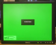
After the Adjust in Progress screen dropped away, some patience was definitely required for the panel to sync up. Wasn't that patient with the 19" 1280x1024 Dell GENESIS UltraSharp, so I should try it again as it might work as well. I moved right on to the 1600x1200 capable 20" version, getting the same blank, dull overall image result that went dark when I shut down the SE. Decided to let it sit until it just up and told me it was unable to sync to the TPD signal, but it did! [:)]

Fun time for this one is about over for now. The SE's video is borked whether the Radius TPD card is in place or not. I get the bong and it must be booting to the :huh: screen as the mouse cursor roams about the TPD portion of the desktop on command. There's no startup disk in the system ATM, so all  drivers needed for basic function are stored on the card itself. Gonna button everything back up and put the card back in the project box until I have time to troubleshoot the SE. I'll leave it out for the day in case someone can confirm that tying R&B together with the Sync/G signal won't kill anything. Solder cup terminated HD15 is bolted up to the BNC/backplane bracket with convenient DE-9 punch in it already and I can make the time for a bit of soldering.

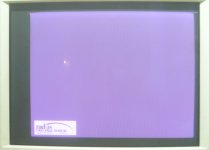
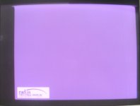
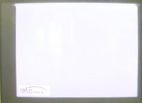
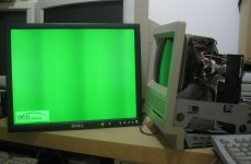
Project started out in the Radius TPD/SE BNC->Monitor connection woes . . . thread for any interested in the TLDR scoop. Thankfully I never got to the woes part. Broke that thread off with this pic  .  .  .

View attachment 27986

.  .  .  but few have a monster MultiSync CRT available. So I figured the LCD test and this new thread were in order so others can share their results. Looks better centered up on the LCD anyway.

 
Last edited by a moderator:

Trash80toHP_Mini

NIGHT STALKER
Thanks, hadn't thought of that. They used notch filters to eliminate the jamming signal from HBO and Sports Channel on cable back in the stone age. Would something similar work to filter sync out of R&B lines? Gonna pull the soldering station out next to check for artifacts. I'm supposed to be cleaning, straightening, organizing and putting my stuff away today! ::)


Gorgonops

Moderator
Staff member
Thinking about it it'll probably be fine. I'd expect any artifacts would probably only show up in the overscan area anyway? Not 100% sure of that.


Trash80toHP_Mini

NIGHT STALKER
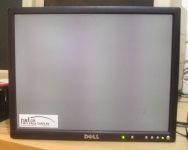
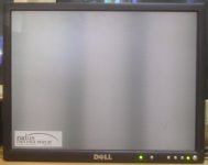
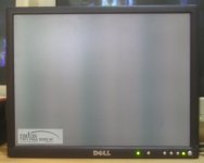
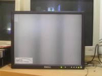
Radius-TPD-SE-White.JPG

Managed to hack it together with breadboard bits. After the splash exits the screen, the plain gray desktop is just b-o-r-i-n-g after its bright green predecessor, but more useful in the long run. There's a long wait before it syncs up, but it gets there. Thought it was FUBAR the first time, wish I'd had the camera up for that one. Screen was in black and white, but horizontal rolled over and wrapped about a third of the way around back to the left side. Front an back porches seemed to be displayed in the middle, very strange and cool looking, but I can't repeat the results. :-/

Panel's got a bazillion hours on it so that's probably the source of the banding.  IIRC the 19" panel is in much better operating condition, so I guess it's one more test before I wrap it up.


Gorgonops

Moderator
Staff member
The specs that come up with Google for the Radius TPD are pretty weird:

Radius TPD 1152x870 71Hz Vertical / 66kHz Horizontal


It's a solid testament to your Dell LCD that it could sync up with that at all. As to the banding, if you don't see it normally (IE, it's not a defect in the backlighting or something) it could also be an artifact of the non-integer scaling it's having to do to fit 1152 into 1600 pixels. I've seen banding kind of like that when displaying "weird" resolutions, like the 1152x800-whatever from my Sun boxes, or the output from the cheapo arcade scaler board I have for the Apple IIgs.


Trash80toHP_Mini

NIGHT STALKER
Yah! Everything about displays was pretty weird from 1984-1990 and then tapered off to just a bit weird until Apple finally surrendered and went with VGA.

19" Dell UltraSharp's not quite as versatile at 1280x1024 as it's 20" 1600x1200 stablemate. Blips and acts like it wants to sync up, but only showa up as a dim field that goes black when I power down the SE. Had the camera all set up to document the weirdness if it cropped up again, but no go. The smaller panel never even got to the Adjust in Progress report, just laid there like a Lox. 4:3 panel works 5:4 panel doesn't, though both have plenty of pixels to do the job. 1152x870 doesn't fit into either camp, strange. I'll check the docs on the 20" panel to see if I can get it to do 1152x870 without scaling to see if the banding is from that or wear and tear.

That's plenty good enough for today, wrapping up and putting it away for another day.


Gorgonops

Moderator
Staff member
The sync-on-green probably doesn't help with the more low-end panel. But, as has been lamented many a time, it's sad how lamed the scalers are in many/most VGA LCD monitors. Many simply flat-out refuse to work with any resolutions that aren't on the VESA standard mode lists.


Byrd

Well-known member
That's great progress, Trash80!  I'm sure a few of us have oddball video cards in compacts/pizzas/desktops that would benefit here from your research.  What model is your Dell LCD, and any fancy adapters etc you made up you could take a pic of?

 
Last edited by a moderator:

Trash80toHP_Mini

NIGHT STALKER
The LCD is a Dell UltraSharp of 2004 vintage Model 2001FP from a craigslist buy something like ten years ago. I bought another 20" UltraSharp to replace it more recently from an outfit that refurbishes and sells stuff that comes in off lease. This may be very good news for those that have cards with BNC connections whatever brand, but the proprietary DE-9 connections on many cards remain a mystery.

Fancy adapter:

View attachment 12658

Ignore the BNC/Phono adapter, I never used it or the standard cable you can see, it's broken anyway. Two F-F breadboard jumpers between headers on the board and pins on the HD-15 cable connector did the trick for the green screen test. The tiny breadboard setup I threw together for hookup of RGB lines to turn the output white is too ugly, overly complicated and much too confusing to document for something that's simple as can be.

 \ | /    If I'd felt like it I'd have cut and stripped the white jumper, done the same with red, green and blue jumpers and twisted/soldered the four together in a

   |       trident form factor. I'll do the real deal with the Solder Cup HD-15 connector I used for documentation when I get a chance.

Update of the riginal conquest thread shows the TPD card setup process most completely:


Trash80toHP_Mini

NIGHT STALKER
Apparently I just just cannot let anything alone until I manage to induce some wonkiness:

Green Screen:

Radius-TPD-SE-GREEN-01.JPG

White Screen:

Radius-TPD-SE-White-01.JPG

Sharpness is the same, just exposure time/jitter/ambient lighting effects, but the distortion across the top is new and interesting.

Pulled and replaced breadboard connections for the heck of it:

1 - Green line only works on breadboard setup as in the simple setup, no problem with baseline signal

2 - Green + Red = distortion free dull Amber Screen reminiscent of my CAD days before the Mac era.

3 - Green + Blue = distortion free dull, Deep Blue Screen

4 - Red + Green + Blue = distortion

LCD apparently masked the distortion, Multisync CRT analog goodness rocks for stuff like this!  [:)]

< tangent generation mode >

Found the proprietary DE-9 connector plague research thread:


While I get any of a dozen other projects squared away, I'll keep a lookout for those cards. Got the SE I was without in January three months later and still haven't gotten around to playing with any of that lot. I've been slowly chipping away at getting the SE, Radius Accelerator 16 and TPD cards set up for display atop the IIfx for sharing the Radius 2150 between them. Looks like a kink or two will need to be worked out for that as well.

< tangent generation mode >

edit: @Gorgonops do you think the banding in the image on the LCD might be its digital way of letting us know about the signal distortion so readily apparent on the CRT?  Images in for comparison:

View attachment 27992

Radius-TPD-SE-White-01.JPG

 
Last edited by a moderator:

Trash80toHP_Mini

NIGHT STALKER
Wondering if it's the lengths of unshielded wiring that's at fault? I'll have to try a short set of twisted pairs with dedicated ground or tie the signals together at the solder cups of  the HD-15 connector.

 
Last edited by a moderator:
Trash80toHP_Mini

NIGHT STALKER
It's officially much worse when R&B are tied together with G at the solder cups of the HD-15 panel connector. It makes for a far shorter, better cable with twisted pair signal and ground

that 's technically much better  .  .  .  it just doesn't work like it's better  [:p]

Breadboard kluge distortion:

BreadboardKluge-Distortion.JPG

Custom cable distortion:  (shoulda' waited until dark to take the pic to match ambient light exposure gremlins?)

Cable-0-Distortion-00.JPG

Not only is the distortion more pronounced, jitter has been induced in that section, which is lower in the scan and once in a while even the Radius PrecisionView 2150 can't sync to the near-FUBAR signal.

Takeaway from this session:

1 - I won't be displaying the SE on top of the pet IIfx or hooking the B&W TPD/SE Card up to the lovely 24bit Radius TPD as I'd hoped to.

2 - Pretty sure this card will need a dedicated display, but not the one it was bundled with from Radius. [}:)]

The LCD side of things is whack-doodle to near max with the newer/better/cable and I documented the color channel variations induced by playing with the breadboard jumpers that I described above:

Custom cable distortion has coalesced into two central bands and at edges with more definition/contracted?

LCD-Cable-0-Distortion-00.JPG

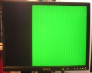
Breadboard kluge distortion with slight spectral banding that's difficult to see in a pic.:

LCD-RGB-Screen-Distortion-Spectral-A.JPG

Green+Blue Screen shows color shift of banding:

LCD-Blue-Screen-Distortion-Position-A.JPG

Green+Red Screen shows another shift in banding:

LCD-Red-Amber-Screen-Distortion-Position-A.JPG

Green Screen shows baseline band position:

LCD-Post-Adjust-bumped-over-Distortion-A.JPG

Whack-doodleage ensues!

LCD-Auto-Adjust-Pre-Distortion-A.JPG

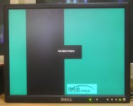
I try to catch the splash screen to watermark all pics. This time I caught it during auto adjustment - look ma, no banding!

At end of adjustment sequence, the image bumped a bit right, now WITH banding! The shot above was taken right after this one for comparison, so no splash screen.

Best for last, I caught the image wraparound I'd reported above, but no light show in the blanking/porch areas this time.

LCD-Rollover-Auto-Adjust-Pre-Distortion-A.JPG

Look ma! NO BANDING during this even Whackier-Doodle Auto Adjust Process!

DEDICATED TPD/SE DISPLAY PROPOSAL:

Hacking this ancient, worn out 20.1" 1600x1200 capable Dell GENESIS UltraSharp Model 2001FP as a dedicated display looks like the way to go at this point?

-  need to set it up to display Radius TPD/SE resolution pixel for pixel, centered on the panel so banding from the scaling process goes away?

-  thinking that tying R&B together with G in digital logic downstream of the panel's Analog VGA Signal->Digital Signal Converter would be the way to get Black and White?

-  thinking that torquing brightness and contrast settings all out of shape will be needed to get a B&W image that's nice and crisp?

Dunno, that's the path I intend to explore if nobody can convince me it's a lost cause.

I'm officially very tired of this schniznit for now.  :blink: I'll wait a bit to button everything up and put it away in case anyone comes up with a test procedure suggested by these findings.

edit: realized the spectral banding shows more clearly in the pic at the top of the thread from my first RGB/LCD tests:

View attachment 27992

 
Last edited by a moderator:
Gorgonops

Moderator
Staff member
I am still relatively convinced the banding on the LCD is the result of pixel scaling and nothing in particular to do with your signal quality. This is a 1 bit monochrome video card, correct? (It's difficult for me to tell for sure because your pictures are so grainy, but I'm assuming that it is because it's in an SE and not an SE/30.) That means that medium gray background covering most of the screen (IE, it's gray compared to the white behind the Radius logo) is a dot pattern, presumably a 50 percent black-and-white mesh pattern? That is *absolutely* the worst case for LCDs to scale cleanly when the resolution is some non-integer division of the native pixel grid, and I don't think you'll ever be able to make it look perfect. I suspect the reason you *don't* see it (as much) when the monitor is in the process of auto-adjusting is because the monitor hasn't settled on the exact multiplier it needs to apply to make the aspect ratio "correct" (by its estimates) and, sadly, some of its rough guesses actually map better because they're closer to integer divisions.


Trash80toHP_Mini

NIGHT STALKER
Makes sense, you'd already convinced me of the banding being a scaling problem and not a sign of age. That's why I'm going to be looking into getting the panel to display the image unscaled. The "better cable" wasn't for the LCD, it was an attempt to get rid of the jaggied distortion at the top of the CRT image that's present only when all three signals, Red Green and Blue are tied together and fed to the VGA cable simultaneously. Higher spec cable made things worse, not better, go figure. Green's required for Sync on Green, but if I unplug either Red or Blue everything is fine but the color.

I can't find the user manual for the Dell 2001FP and the data sheets/specs I have found don't mention anything about a menu for tweaking settings. Might it be possible to disable scaling on the controller board? Pixel for pixel centered up on the screen would be probably be the best case scenario. What do you think about tying RGB together on the digital side of things? If I could get those two mods to work I'd fake up a CRT Bezel/Case in a very shallow CRT lookin' case hack and call it a day.

Yes, it's a B&W Radius TPD Card for the SE per the thread title.  [;)] The splash screen for every card in my fairly extensive Radius VidCard collection has that same even gray background.

Tried it on the 21" MAG that has LCD readouts and got it to sync up once or maybe twice? License plate in the corner looked good, but the background was very dull. Seemed to be centered much better than on the 2150 though. Readout said it wasn't a cataloged setting. Can't duplicate the results so that's a no-go.

Now I've got a bug in my ear nagging me to snag a BNC equipped Radius FPD Card just to see what happens. Gotta check the Radius drawers first though.

 
Last edited by a moderator:
Gorgonops

Moderator
Staff member
What might be causing that tearing when you have the single line feeding all three inputs is beyond my bailiwick, alas. I kind of wonder if you might be getting some sort of feedback or ringing from simply bridging the inputs on the monitor together that the newer circuitry in the Dell is more immune to, but analog circuitry just isn't my strong point. The other thing I kind of wonder about is if the sync pulses are negative or positive; if they're negative the red and blue inputs on the monitor might not be equipped to handle that and when they get the negative excursion it freaks something out. Over the long term that might be bad for the monitor. If you had an oscilloscope handy I'd suggest getting a picture of the sync pulses and see.

Maybe you could stick some diodes on the R&B lines? Problem with that is there'd also be a voltage drop from that, which would make the intensity different from the green line. Do you know what the output voltage swing on that card is? There's certainly a chance it's larger than the standard 0 - +.7v nominal that VGA monitors expect.

 
Last edited by a moderator:
Gorgonops

Moderator
Staff member
What do you think about tying RGB together on the digital side of things? If I could get those two mods to work I'd fake up a CRT Bezel/Case in a very shallow CRT lookin' case hack and call it a day.
I doubt there's anywhere on the "digital side" you can do that. I'm sure the feed from the VGA port goes into an absolutely huge signal processing ASIC that does magic beyond the keen of man and passes all its signals via a few hundred BGA solder balls.

A stupid hack that I suspect would produce too dark of a display: the controls on the CRT don't let you just turn down the color intensity to the point that you can render the green feed as monochrome, do they? Since you're dealing with a single bit display it seems within the realm of possibility that drastically abusing the controls *might* produce a passable picture with just a green feed.

 
Last edited by a moderator:
Trash80toHP_Mini

NIGHT STALKER
Yah! Doing just the green thing crossed my mind several times to no avail. First thing is to unhook my main display and give it a whirl. I've already got it set up for doing pixel for pixel and that let me do 1920x1200 from the VGA feed on my Notebook instead of the 1600x1200 that was letterboxed before I banged on the control panels with a wrench. Come to think of it I can just carry the SE in here if I clear off some desk space. ::)

< scuffling, cursing, generally noisy interlude >

Couldn't resist, realized I could use the printer stand instead of the desk. High end HP ZR24w was a bust, I hooked it up with the breadboard kluge and got bopkes. But the other 1600x1200 20.1" Dell is sitting right next to it. Hooked it up and got some truly strange results. This one's a 2001FF, the other's a 2001FM for whatever that's worth. We're talking ragged edge case here. After a rough start, the first time or it synced up I couldn't believe my eyes, rock solid Green Screen with no banding! Then it was back to your usual banded programming and a lot of those rough starts. Definitely not usable while the "old" model has quite a bit more slop from its bazillion hours of up-time or whatever difference there may be between models.

Rough start with banding reminiscent of the first CRT trials from the previous incarnation of this mess of a thread:

Dell2-Offtoaroughstart-10043.JPG

Rock solid background after a jittery splash screen:

Dell2-RockSolidafterjitterysplash-10044.JPG

Back to the banded blues again:

Dell2-Backtoyourusualprogramming-10045.JPG

No tripod this time around so it's grainy and blurry. I've just been taking screen shots at whatever magnification to reduce file sizes instead of doing it right in GraphicConverter over on the QS. It's a pic heavy thread and I'm at 62% of my data allotment for attachments.

Here's the pic from the start of the previous thread:

View attachment 12659

Not the same on the 2011FF, but it reminded me of this pattern.

Seems like there's gotta be some way to tie RGB together in the old girl, wedge a hack at the LVDS cable maybe?


Trash80toHP_Mini

NIGHT STALKER
Ran through the thread again and it looks like I've lucked into enough data already posted to show the banding is caused by scaling/sync combination:

Note position of the vanity plate after scaling/sync has been established and showing artifacts. Sync'd image appears to be a tad shifted to left, I'll need to check for that.

View attachment 28036

note vanity plate position before scaling/sync process is complete. Image is off center, back porch visible on right

View attachment 28040

a tad earlier/later in the sequence? Note  what might be a subtle difference in radius of rounded rectangle? Could be induced by combination of Blue/Green?

View attachment 28041

Not conclusive on any front, but the wonkiness looks to me like scaling/horizontal roll correction and then final sync add up to funkiness going on within the controller, so the insanity of hacking the colors together at the LVDS signal level won't do the trick.

Looks like my best results were with the custom cable after all

AP1010034.JPG

The bands are more refined, tighter and show far less spectral spread. I'll have to revisit this setup before signing off on this session. Makes me wonder if that LVDS hack to break R&B channels out from green digitally might establish a solid line pattern, two centered and half of the third band on leading and trailing edges? We'll probably never know, that's a non-starter unless an unscaled, letterboxed image can be established.

 
Top