• Updated 2023-07-12: Hello, Guest! Welcome back, and be sure to check out this follow-up post about our outage a week or so ago.

PowerBook 1400 LCD replaced with New Old Slightly Different Stock

AEChadwick

Well-known member
I am an idiot with LCDs, but this actually worked so i thought i would share.

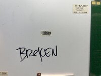
I obtained a PowerBook 1400c, hoping to harvest the active matrix LCD, but the screen was busted. The LCD pulled from the 1400c was a SHARP LQ11S42. I have not seen a list of the LCD screens used in the different 1400 models; and this was the first time i’d paused to notice the model number.

With the insight of a post listing 500-series LCD Model numbers, i recently found a NOS replacement for a 540c LCD. i figured it was worth searching for a replacement LQ11S42.

However, I could not find a source for the "SHARP LQ11S42"--just a few generic LCD-supplier-sites with "call for an estimate", or prices like "$245 + shipping, 0 in stock" and other fake-outs.

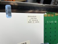
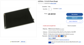
An eBay vendor from which i previously found spare parts randomly had a few SHARP LQ11S46--a couple digits off? Superficially, the LQ11S46 stats were identical: 11.3", SVGA, 800x600; and it appeared to have the same connector on the back. Best of all, it was only $17, cheaper than eggs and more entertaining.

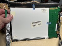
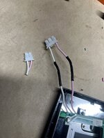
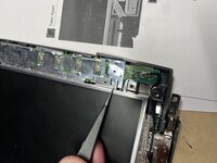
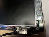
The LQ11S46 arrived today and i swapped over the cables from the broken 1400c. I attached it to my G3-upgraded 1400cs/133. (only the backlight cable connector was different, quick surgery.)

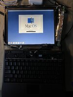
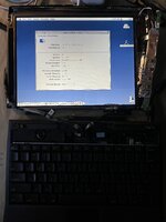
It works perfectly and looks great.

Was the LQ11S46 also used in the 1400 series? I don't know what it might be doing differently, but for now I finally have a PowerBook 1400c/G3.
 

Attachments

  • Original_LCD.jpeg
    Original_LCD.jpeg
    3.1 MB · Views: 45
  • replacement_LCD_number.jpeg
    replacement_LCD_number.jpeg
    2.8 MB · Views: 41
  • replacement_LCD.jpeg
    replacement_LCD.jpeg
    3.2 MB · Views: 44
  • Replacement_LCD_Source.png
    Replacement_LCD_Source.png
    559.7 KB · Views: 45
  • swap_power_connector.jpeg
    swap_power_connector.jpeg
    1.8 MB · Views: 49
  • 1400_Boot.jpeg
    1400_Boot.jpeg
    1.3 MB · Views: 42
  • 1400_System_Profiler.jpeg
    1400_System_Profiler.jpeg
    1.5 MB · Views: 49

LaPorta

Well-known member
It may have been. I forget that number, but I also sourced some replacement LCDs for my 1400 that are sharp, but are a different revision that have only one capacitor instead of two on the back.
 

Paralel

Well-known member
I'm glad it worked out. A panel from around the same time period with the same apparent specs and connector should work, but sometimes the smallest differences end up causing trouble, it's a crapshoot. I'm not too surprised that the grafted connector worked since they are both two pin, and backlight connections are usually fairly simple. Strange that they chose a 3 pin connector and just left the middle one blank.
 

aladds

Well-known member
Do the 1400cs and 1400c have the same cable/connector at the screen end? This would be really cool as a cheap upgrade path!
 

AEChadwick

Well-known member
the parts have different numbers in the tech manual, so i expect those are not interchangeable.

i used this LCD and the cable from a 1400c to upgrade a 1400cs--so the motherboards are fine with the change.
 

greystash

Well-known member
Do the 1400cs and 1400c have the same cable/connector at the screen end? This would be really cool as a cheap upgrade path!
From memory the display cable connects at a different location under the bezel. I tried years ago to put an LCD from a 1400c into a 1400cs but it wouldn't work because of the connector position. I don't think I had a 1400c at the time so maybe if I had the longer display cable it would have worked.
 

LaPorta

Well-known member
I know for a fact that they are not interchangable. That being said, if you are able to source a 1400c LCD to logic board cable as well, that should work just fine.
 

Snial

Well-known member
Do the 1400cs and 1400c have the same cable/connector at the screen end? This would be really cool as a cheap upgrade path!
So, I've managed to note that you're talking about cable/connectors at the screen end. As it happens I bought a 1400cs from Ebay last November / December. I spent a bit of time swapping out the HD (after backing it up), then replacing it with an IDE to SD adapter (it's a little bit slower than the HD should be, but is very quiet). Then I bought a non-working PB1400c/133 from Ebay with a 16MB RAM expansion. I thought it had an internal CD, but it didn't (just another battery in the other slot), but the RAM worked (CPU didn't). I removed the PB1400c's screen and replaced my PB1400cs's screen, which has worked very well since!

The LHS cable braiding is frayed on the PB1400c's screen, so I plan to fold the screen only occasionally. But in theory, obviously the cable signals are compatible.
 

AEChadwick

Well-known member
Well there’s the difference: the lower mounting tabs are about a centimeter off.

Doesn't matter much on the left; on the right, i fixed it with a dremel.

(The bezel is tight enough, the screen stays in place just fine without the lower mounts.)
 

Attachments

  • IMG_3993.jpeg
    IMG_3993.jpeg
    2.7 MB · Views: 30
  • IMG_3994.jpeg
    IMG_3994.jpeg
    2.8 MB · Views: 29

MacUp72

Well-known member
I wonder what displays of other Powerbooks actually are compatible for the 11,3" 1400..from the 5300c?..no they are 10"
 
Last edited:

jeremywork

Well-known member
IIRC the cs bezel is slightly different than the c bezel too. They’ll swap just fine, but will obscure the very top or bottom row of pixels.
 

CircuitBored

Well-known member
IIRC the cs bezel is slightly different than the c bezel too. They’ll swap just fine, but will obscure the very top or bottom row of pixels.

Correct but it is not just a single pixel line that is obscured. You can also see the metal lower lip of the display (when putting a c screen into a cs chassis). I found it to be far too visually "off" to be happy with it so I just used the entire c display assembly on the cs body in the end.
 

3lectr1cPPC

Well-known member
Strange that they chose a 3 pin connector and just left the middle one blank.
Sorry about the bump - realized why this likely is. It's probably to prevent against short circuits. Lots of high voltage going through there, and it's a lot less likely to short out in the event of damage to the connector if there's a pin of separation between them.
 
Top