-
Updated 2023-07-12: Hello, Guest! Welcome back, and be sure to check out this follow-up post about our outage a week or so ago.
You are using an out of date browser. It may not display this or other websites correctly.
You should upgrade or use an alternative browser.
You should upgrade or use an alternative browser.
Macintosh Portable power regulation
- Thread starter Mc128k
- Start date
aplmak
Well-known member
Techknight is going to yell at you guys for using the gray power bricks!!! I think even with the adjustment inside.. If you value your portable and want less head aches you really should stick to the original white (only) portable a/c adapter.. why chance it! I'm sure you can find one on ebay.. The gray ones have been known to slowly damage them... They are not made for the portable.. they will work but your portable will eventually fail. It's a slow death sometimes....
If you think you know better then by all means go for it..
If you think you know better then by all means go for it..
Last edited by a moderator:
Rajel
Well-known member
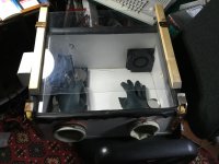
Inquiring minds... I remember reading a build article for a small hands-only clean chamber awhile back, but that was long ago.Opened in my homemade clean room
How'd you build yours?
techknight
Well-known member
You could use a clear tote for this too. I've seen a few people do it that way too.. whatever works.
Ziggystar12
Member
Best thread ever!
Ziggystar12
Member
Two follow up questions.
What is the situation when your floppy drive won't boot and runs slow? I've seen two boards doing that now. Scsi boots fine. Machine is happy Mac otherwise. Internal and external floppy ports suffer the same. Even a floppyemu won't work. Is there an ic to blame?
What does the 16-18 pin 1k resistor trick do, when should I use it?
Mc128k
Active member
Two follow up questions.
What is the situation when your floppy drive won't boot and runs slow? I've seen two boards doing that now. Scsi boots fine. Machine is happy Mac otherwise. Internal and external floppy ports suffer the same. Even a floppyemu won't work. Is there an ic to blame?
What does the 16-18 pin 1k resistor trick do, when should I use it?
About the floppy I would start a new thread, as this isn't related to power regulation. I haven't investigated on it, but if you follow the first scheme I posted you should be able to check if there is power first.
16-18 as you can read from techknight's posts is a hack that kickstarts the IC chip into oscillating. As this is a power-saving IC, it compares the values periodically, and not in a continuous mode. Sometimes it gets stuck it seems, and this trick gets it back to checking the input values. Check out the datasheet if you need more info.
Mc128k
Active member
Another thing, just to update the topic. The lead-acid cells have arrived and I reassembled the battery pack. It just works perfectly, so absolutely no IC/FET/Transistor was harmed during my awful experiments.
So... it is done now. Everything in full working order, just like new.
I also see that using the bench power supply the computer actually asks for more than 1.5A, so a limiting power brick is mandatory in every case. Like somebody wiser said.. do not use the gray brick. Ever.
So... it is done now. Everything in full working order, just like new.
I also see that using the bench power supply the computer actually asks for more than 1.5A, so a limiting power brick is mandatory in every case. Like somebody wiser said.. do not use the gray brick. Ever.
Ziggystar12
Member
Forgot to mention, if you boot to scsi it works but I get the Mac will shut down in 10 seconds message with a full battery and plugged in. So maybe still related to power regulation? Do you solder the resistor or just touch temporarily?
Last edited by a moderator:
techknight
Well-known member
As far as the floppy drive, the SWIM IC is a known failure point in the Portable.
You can find an old SE/30 board or a IIsi board or something that got battery acid exploded, you can pull and swap the SWIM ICs. That should fix it.
You can find an old SE/30 board or a IIsi board or something that got battery acid exploded, you can pull and swap the SWIM ICs. That should fix it.
Ziggystar12
Member
Theoretically if one inserted a ram card while the 9v backup battery was active, (big pack removed but battery lid open) would that blow out this swim ic?
techknight
Well-known member
it shouldnt.
But I do know that on those machines, if 1 of the 2 red wires loses voltage, it can fry the SWIM, I have witnessed it first hand.
what it does it cause the 5.2V to lose regulation, and will show AC adapter voltage at 7.5 to 7.8VDC, and the SWIM gets hit first.
And to be honest, after following a couple threads, the wiring harnesses are starting to become problematic, Whether its the microswitch or whatnot.
The microswitch if I recall is double-throw. Meaning there are 3 wires that go to it.
If the microswitch gets bad to the point to where the normally closed position is open as well as normally open, it CAN cause the 1-wire only voltage situation which frys the SWIM and causes a shitload of other regulation problems.
Last edited by a moderator:
Ziggystar12
Member
So why not tie the two red wires together either in the bundle or on the motherboard? I thought one Input was for the 9v battery only and the other for the large battery? Does using only the large battery with no 9v fry things?
Mc128k
Active member
No, the wires are soldered together at the microswitch, any failure of the switch shouldn't impact this, the cables remain shorted.
They both give 6.5V from the lead acid battery OR the 9V battery when flipping the switch. The 9V voltage is dropped by two diodes on the wire.
They both give 6.5V from the lead acid battery OR the 9V battery when flipping the switch. The 9V voltage is dropped by two diodes on the wire.
Last edited by a moderator:
techknight
Well-known member
Then there have been changes over the years, because mine are not wired like that. Only 1 of the wires switches over to 9V from 6V while the other one is hot 6V all the time unless you remove the battery.
Last edited by a moderator:
Mc128k
Active member
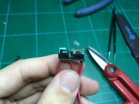
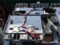
Weird, I thought I had the first version. As you can see here, the two wires on the right are soldered together and they go directly to the board. I presume that if you had them separated there could be issues when the main battery was connected without a backup battery (the frying you were talking about), so they had them joined while keeping a hot wire and a smaller one. Just a thought.

This is the rebuilt cable, as before both wires are soldered at the switch.


This is the rebuilt cable, as before both wires are soldered at the switch.

Ziggystar12
Member
What diodes did you add to drop the voltage of the 9v? My wire had the diode a while back but the diode burned out and I didn't replace it. I thought it was just a protection diode.
Similar threads
- Replies
- 17
- Views
- 1K

