• Updated 2023-07-12: Hello, Guest! Welcome back, and be sure to check out this follow-up post about our outage a week or so ago.

Macintosh Portable power regulation

Mc128k

Active member
Hi everybody

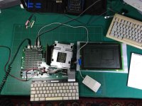
I recently obtained from a friend a Macintosh Portable in perfect conditions, and I am currently trying to bring it to life (even if it's useless! Yes, I am wasting my time, got a problem?). It's the very first model, the one with no backlight.

First thing first, I disassembled it, and it was a joy. Found immediately a huge leak from the 9V battery, that hurted the logic board underneath a bit. 

Washed, cleaned with isopropyl alcohol and fully recapped. About the power supply, I am using the lower right connections (the test pads) to deliver about 6.5V with a lab power supply limited to 2A (tried with the red cable first, and then I saw it's the same thing).

The machine can actually power on (I'll omit various steps I tried to power it on, because I really lost hours into this repair), but after one second it shuts down. No signs of life, no PRAM fix. I have to disconnect the power, wait a few seconds, and then reconnect it again.

So.. I decided to try reverse-engineering the power circuits. Here is the result so far:
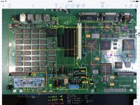
IMG_0468.jpg

It seems that the portable has a linear regulator for the 5V line, and a switching boost converter for the 12V hard disk power. The problem is that what is seemingly 5V (orange line) reads 6.5V (the power supply voltage). So the Q16 P-MOSFET is completely open. Bad.

The gate measures almost 0 volts, that means that Q16 is not receiving the correct signal I think. Who gives that signal? U1M

Also I can see with an oscilloscope (a piece of junk actually) that Q20 starts high (so it's off) and then it starts oscillating at about 2V when the machine powers off. No problem, it seems to be only related to the hard drive (5V probably).

In the hybrid IC U1M, the upper right controller drops the voltage at the shutdown point, the FET below it stops delivering power.

Now, I believe I did something wrong here. I don't know what because I experimented a lot with this board. I can just say that it's surely a power issue because I have seen it working with the original hard drive in one particular test (it loaded the OS!), and after that it stopped. Maybe one of the tests burned some op-amps, I don't know and I have no way of testing it.

There is no schematic and the board is multi-layered. This makes any reverse engineering work a hassle. I hope this partial schematic could come useful to somebody.

I already read a large number of posts and seen some troubleshooting videos. Cannot get any clue, my electronics debugging skills are poor here.

Maybe it's time to call for help. I'm really stuck here, and I see no way out (building a separate power supply and disabling the board mosfets is too extreme). Any help would be useful, I'm not a noob and I'm not asking for step-by-step instructions. Just some hints on where to look for issues.

[Probably someone is going to say that it's the hybrid IC. Hooray! Not helping]

Thanks

[EDIT]

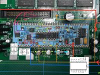
Also checked and rebult some VIAs in the upper left part where the chip is missing (this is a work-in-progress picture, I didn't connect it like that).

The speaker crackles if I use the MOLEX plug (which shorts the first two 6.5V contacts), and it works fine if I power directly 5V to the orange line. Unfortunately some of these tests made Q16 emit a buzzing noise (disconnected immediately of course), like a circuit was oscillating in a bad way; it's alive then..?

 
Last edited by a moderator:

techknight

Well-known member
You absolutely HAVE to use BOTH pins (1, 3) on the molex to power this board! It will NOT operate any other way!  

You will fry shit if you dont. Trust me, been there done that. I have seen quite a few of these boards where exactly THAT has happened flow through my hands, and I cant get away without replacing a handful of logic ICs before it works again. Because the portable sees 6.2V instead of 5V. thats BAD. 

And if you had already attempted it (which it appears you did) its probably fried now anyways. 

 
Last edited by a moderator:

Mc128k

Active member
Then probably I did fry some components. I kinda imagined it later on, but it's nice to have your confirmation.

Using both pins brings the board to the quasi-initial state, which is:

  1. Board off
  2. If I give power to the MOLEX connector and then immediately press a button, the computer will turn on for less than a second and then die
  3. Successive presses give absolutely no signs of life
  4. Even if I disconnect and reconnect the plug and/or reset the PMU.
  5. The only way to get it back is to discharge C27, and then it's back again to step 1
This was what the board did before using the single pin (the test connector, which I won't use anymore now), and that tells me that probably:

  • It's not fried
  • It was already fried, since the symptoms are the same as before
  • Something else got fried, but is excluded from this stage

I might add that I see a signal coming out of the U1M that when reaches a certain threshold then the power is cut off from the right controller, and subsequently to the entire board. Having no schematics It's difficult to say what could it mean for that signal to rise.

 
Last edited by a moderator:

Mc128k

Active member
Further testing revealed something rather interesting:

If I discharge C26 and C27 (C25 consequently too), and then start right after powering up (6.5V), the mac actually starts and stays in the boot screen! It shuts down after five to ten seconds. If a hard disk is connected it spins up and dies after one second. The 5V line works fine.

Tried afterwards with 6V and it shuts off after like 500ms. Back to 6.5V... same.

Techknight, I don't want to stress you with my problems, do you just have an idea about what these caps actually do?

 
Last edited by a moderator:

techknight

Well-known member
But thats because the PMU isnt getting the battery detect signal, or the PMU's ADC isnt seeing the battery level that comes from the Hybrid. 

So its going into low power shutdown. Since you get a boot screen asking for a floppy, that rules out 99% of the logic. Whew...

If any of the logic ICs were fried, you would NEVER make it that far trust me. you would get a pixilated display, black bars, or solid black display if you got anything at all. 

What I need you to do now, is check the voltage at the Hybrid, on the pin literally behind the NMI button. it goes into that Op Amp sitting below. It should hover around 2.2 to 2.5VDC. if it falls to 0, or latches at 5V, the system will NOT stay on. 

If that looks good, I then need you to check for roughly the same voltage at the PMU on Pin 52. The signal gets filtered by a low-pass sitting at R151 and C107. if anything is wrong there youll get issues. 

This should help you out: 

Power Manager.pdf


Attachments

  • Power Manager.pdf
    122.5 KB · Views: 94
Last edited by a moderator:

Mc128k

Active member
Yeah, the logic looks intact. Low power? That could really be the case!

About fried stuff I am referring to the power circuitry. I know how these old machines behave with bad digital ICs (repaired two classics and an LC a few years ago), luckily this doesn't seem the case.

[Now, that PDF is rather interesting..! I believed Apple Schematics were as real as unicorns or honest people]

Anyway, I did the tests, and indeed the voltage drops immediately. It maybe reaches 2V but only for a fraction of a second, it drops to zero in no time.

I measured the top left pin of U1M. The second gives 0V.

The two op-amps are powered by the... output of one of the big ones. Didn't figure out what they are comparing, but they have a common input, the light blue wire that connects with the green pin under the keyboard connector. That explains why discharging the caps make it work.

The first output goes to the 5V linear regulator, while the left one... to the first pin... and then waaaay to the right, I lost the trace. [EDIT: it goes to R151...]

IMG_0470.jpg

Anyway the signal goes to zero after a short time. When I can get the system to boot (after waiting for all caps to discharge), I see that the signal becomes stable at 1.5V approx. and then it starts dropping slowly (the system shuts down) until it reaches 1V and it becomes stable. This signal is very correlated to the system behaviour.

Oh and thanks for the help! :)

[EDIT] Also I see that R151 is near an area that I recapped and cleaned, maybe there is some rotten VIA here, I'll check it the next time I get my hands on the board. Now I'm going to sleep...

 
Last edited by a moderator:

techknight

Well-known member
Faulty Hybrid. 

Now the Hybrid is a mystery because I do not have that in my apple files, as it was never documented officially. Must have been outsourced like from Sony or something. 

Stick a 1 Meg resistor between pins 16 and 18 of the LTC1040. 

 
Last edited by a moderator:

techknight

Well-known member
I was looking closer to your picture, thats either a hair, or the hybrid is cracked. Take a look behind the 2 buttons next to the op-amp. 


Mc128k

Active member
Hair (yup, still awake..). I read about your 16-18 solution, but I was hesitating.

I'll try that one.


techknight

Well-known member
Also, check the 0412 voltage reference. it should be 1.1 or 1.2V very close to that, and not wavering around. 

If that is ok, then it is possible that the op-amp for the battery monitoring circuit is bad. I have seen it, rare. but can occur. 

the right adjacent op-amp is for the 5.2V B+ regulation. 

the LTC1040 serves 2 purposes. its the low-voltage lockout, if the battery gets below 5.6V, with or without the PMU, it will latch into lock-out state and drop the 5.2V regulator to 0v. 

It also monitors the DC jack and issues whether the battery needs charge or not. it will latch the charge state, and pull the battery charging signal back to the PMU low. 

But the LTC1040 comparator is a sample-and-hold type, and thats what the pins 16 and 18 do, is form the R/C network for the internal oscillator. If this IC stops oscillating, or oscillating VERY VERY slowly, you will be stuck in between states, or a bad state. 

 
Last edited by a moderator:

Mc128k

Active member
Haven't posted an answer for a while. The little bitch is now working.

I was going to start making the tests you mentioned and after connecting the power supply with a slight higher voltage it actually started remaining on!

...and it holds the hard disk...

...and it boots... ...asks for the additional ram card... it works...

So.. that spoiled all the fun for now :(

6.8V seems to be good for him. If I go back to 6.5V the system tells that it's going into stop mode after a few seconds (and it does), I guess that voltage is too low for the mac.

I don't know if everything else is allright, after all the serial port seems broken (no appleshare), so I'll check everything and post here if there are news.

Again, thanks for the help Techknight!

IMG_3372.jpg


Mc128k

Active member
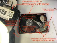
The hard drive had a leaky liquid from the border and a rotten rubber near the magnets. Opened in my homemade clean room, removed the goop and cleaned with alcohol, replaced the rubber with tape, sealed with hot glue. It works beautifully. About the serial port, it was the rightmost, and it suffered injuries from the leaky battery. Four VIAs were destroyed along with some traces, had to rebuild them up, and now it sees LocalTalk and (or) the printer. Also cleaned the floppy and started washing all non-electronic parts. I'll reassemble it soon.

If it could be useful for somebody else (as rotten VIAs are very common), to perforate the VIA I used a modified needle (made it thinner with a drill) and inserted it into the hole. Just use it as a drill bit, rotate and press lightly. Very useful in the case of holes filled up with oxide or battery goo. This can perforate solder if at the other side there is a contact pad.

After making the hole, use an insulated copper wire (take it from a transformer) to connect the sides. Scratch the traces and solder the wire to them.


Mc128k

Active member
FOUND THE ORIGINAL PROBLEM THAT WAS THE CAUSE OF EVERYTHING.

The power cable.

...yep, corrosion does that too. The switch has some internal resistance. Maybe the wire too. I'll rebuild it from scratch.

Likely the computer saw this as a rapidly-discharging battery.


techknight

Well-known member
umm yep. that switch in the rear locks out one of the two red wires to the 4-pin connector, I have yet to see one of those fail, but its 30 years old with everything else so thats not surprising at this point. 

Also the missing heatsinks on your voltage regulators are sure to leave you in for a good time later! 

 
Last edited by a moderator:

Mc128k

Active member
Don't worry, I just removed the heatsinks to check the fet temperature, they are back now. And it wasn't just the switch, when I first connected the lab power supply I attached the wire to the "end" of the switch, bypassing it. It was actually the entire cable that made the mac believe the battery was discharging, it had a high internal resistance.

I'm buying the lead-acid cells now, and if I get the right parts I'll repair the power supply. I have many of those around, was it the 1.5A or 2A version?


Ferrix97

Well-known member
The Power Supply for the portable needs to be limited at 1.5A, only the white brick is recommended. The gray PowerBook ones deliver 2A or more and can damage the Portable


bibilit

Well-known member
1.5A / but the grey Powerbook can be used if the correct A is delivered, adjustment can be made in voltage outputs and Amps inside the power brick.
 
Last edited by a moderator:

Mc128k

Active member
Mine had a gray brick for sure, I just confused it with the others. Didn't know there was a white one. Or maybe it was a replacement

 
Top