-
Updated 2023-07-12: Hello, Guest! Welcome back, and be sure to check out this follow-up post about our outage a week or so ago.
You are using an out of date browser. It may not display this or other websites correctly.
You should upgrade or use an alternative browser.
You should upgrade or use an alternative browser.
Macintosh 128k issues
- Thread starter Sherry Haibara
- Start date
techknight
Well-known member
you had a much better chance of frying it when it was in there with the wrong pinout 
Ferrix97
Well-known member
Sad news: nothing changed. with the 1K resistor it still reaches 63Vac and then starts flubbing.
maybe tomorrow I'll rig up an isolated oscilloscope and I'll probe the output.
(I don't have an isolation transformer, but I could power the scope with a UPS detached from the mains)
I think it was already soldered in the correct way, they placed a K on the silkscreen and I used the schematic for double checking.
techknight
Well-known member
Well the 2N5064 datasheet has a different pinout from the E0102. its also possible the 2N5064 is damaged from previous attempts.
Here is the E0102 series datasheet for your reference just in case your wondering:
http://pdf.seekdatasheet.com/88889/44329.pdf
Also the P0102 isnt the same as E0102. P0102 is the same as 2N5064.
Edit: the P0102 has a minimum of 5uA of trigger current. Way too low. needs to be 200uA+
Here is the E0102 series datasheet for your reference just in case your wondering:
http://pdf.seekdatasheet.com/88889/44329.pdf
Also the P0102 isnt the same as E0102. P0102 is the same as 2N5064.
Edit: the P0102 has a minimum of 5uA of trigger current. Way too low. needs to be 200uA+
Last edited by a moderator:
Ferrix97
Well-known member
Thanks for the datasheet.
comparing the characteristics between the two, I don't see that big of a difference that would cause such problems
I've also tried a P0102 and it still behaves exactly the same way, and those are pretty much identical
(http://www.st.com/content/ccc/resource/technical/document/datasheet/a6/df/6b/a7/cf/54/46/9e/CD00217834.pdf/files/CD00217834.pdf/jcr:content/translations/en.CD00217834.pdf)
Last edited by a moderator:
techknight
Well-known member
no they arnt. Look at the trigger current. You would need to change the triggering resistors to match it. it begins to trigger at 5uA, well before the 200uA of the E0102.
That may be your issue. E0102 uses a minimum of 200uA, whereas all the newer stuff uses a MAXIMUM of 200uA, making a minimum much lower...
That may be your issue. E0102 uses a minimum of 200uA, whereas all the newer stuff uses a MAXIMUM of 200uA, making a minimum much lower...
Last edited by a moderator:
techknight
Well-known member
my advice at this point with a minimum of 5uA trigger current, would be to put potentiometers in place of the trigger resistor networks, and retune the system.
techknight
Well-known member
R44, R45, and R60 probably need tweaked.
Q9 turns on harder when the regulation gets closer to 12V, or even above, Allowing current to flow through R45, latching the SCR.
R45 is where I would start.
Q9 turns on harder when the regulation gets closer to 12V, or even above, Allowing current to flow through R45, latching the SCR.
R45 is where I would start.
Last edited by a moderator:
Ferrix97
Well-known member
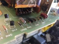
Here's a picture of the carnage:

This leads me to believe that the original SCR might not be a E0102.
The front is blown, so I thought it was an E0102 by reading this post: https://68kmla.org/forums/index.php?/topic/20838-macintosh-128k-240v-analog-board-component-identification/?p=211733
I could solder a trimmer instead of R45, but I don't think going under 220 Ohms is a good idea
techknight
Well-known member
I think you need to go greater than >1K for the R45. Not lower. Lower would cause it to trigger sooner.
Ferrix97
Well-known member
I'm not an EE (I study telecommunications), but I think I should increase the resistance on the gate (by adding a resistor) to limit the current and lower R45 to bypass some current around the gate cathode junction, to make it less sensitive
Last edited by a moderator:
techknight
Well-known member
There is no gate resistor for a reason, the circuit is already setup and tuned to operate in a certain window. You can adjust the resistors that are already there and make it work fine. I would start with R45.
And for the record, I am an EE. My day job.
Curious what I build? Well. Ill show ya!
https://www.facebook.com/majordisplay/
And for the record, I am an EE. My day job.
Curious what I build? Well. Ill show ya!
https://www.facebook.com/majordisplay/
Last edited by a moderator:
techknight
Well-known member
I was looking in one of larry pinas book, describes the operation of Q10, etc...
Personally I dont like the design of this switcher supply. Probably since it was the early days of SMPS supplies, it used a crazy method to make it work. However, I refuse to believe that SMPS PWM controller ICs didnt exist in these days, so maybe it screams cheapness as well..
Personally I dont like the design of this switcher supply. Probably since it was the early days of SMPS supplies, it used a crazy method to make it work. However, I refuse to believe that SMPS PWM controller ICs didnt exist in these days, so maybe it screams cheapness as well..
Last edited by a moderator:
Ferrix97
Well-known member
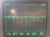
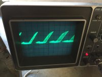
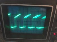
Here are a few measurements:
Unfortunately my digital scope is not isolated and the Idea I had in mind (hooking it up to a UPS) only lasted for a few minutes.
So I had to use an old 15Mhz Philips with a million hours on the CRT
This what I get on the Gate of Q10

This is test point 6 (according to Apple's schematic), or the emitter of Q9

This is test point 5, or the base of Q11

Unfortunately my digital scope is not isolated and the Idea I had in mind (hooking it up to a UPS) only lasted for a few minutes.
So I had to use an old 15Mhz Philips with a million hours on the CRT
This what I get on the Gate of Q10

This is test point 6 (according to Apple's schematic), or the emitter of Q9

This is test point 5, or the base of Q11

techknight
Well-known member
ok, then try going the opposite way... You will have to experiment here because it appears the circuit is very sensitive to the exact type of SCR you use.
techknight
Well-known member
Then absolutely none of this is making any sense. if it works with the original, but not replacements then somethings wrong somewhere...
Also, to re-iterate the pins 1 and 3 on modern triacs are swapped compared to the original E0102. Thats all I can say.
Also, to re-iterate the pins 1 and 3 on modern triacs are swapped compared to the original E0102. Thats all I can say.
Last edited by a moderator:
Similar threads
- Replies
- 18
- Views
- 1K
