• Updated 2023-07-12: Hello, Guest! Welcome back, and be sure to check out this follow-up post about our outage a week or so ago.

Mac IIci PSU recap advice

bigmessowires

Well-known member
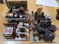
Anyone have a list of caps in the IIci PSU (Astec version), or a walk-through of the process? After disassembling the PSU (a complex enough job by itself), I was surprised by the complexity inside. There are four separate PCBs and something like 30 individual caps. Many of the caps are completely covered in heat-shrink or with glue, so I can't always tell their values or even what's a capacitor vs some other type of component:
20190414_141601.jpg

I found a thread here that discusses a IIci Astec PSU, but the photos of the internals look quite different from mine. The main PCB has a 1990 copyright date, whereas the one in my supply says 1988. So I'm not sure it will be much help.


I've never seen caps wrapped in heat-shrink tubing like this before. Any ideas what the purpose of that is - maybe insulation or vibration resistance? Any reason not to cut them all off so I can better see what's what?

What would you do if this were your computer? Try to identify specifically what's failed? Bite the bullet and try replacing everything? Search for a used PSU on eBay? Chuck the PSU and try to retrofit an ATX supply? My patience for an extended recapping project is low, which is why I was searching for an existing discussion or documentation of recapping this particular model of PSU.
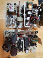
20190414_141544.jpg

 
Last edited by a moderator:

UnaClocker

Active member
Advice.. Don't bother. I spent like $50 to replace all the caps in mine. Still dead as a doornail. What a waste. A microATX power supply PCB fits inside the housing quite well. Way more efficient, compact, reliable, and higher output.


bigmessowires

Well-known member
Argh! Sorry to hijack my own thread, but now I really need help. My original problem (described in another thread) was a recapped IIci and a recapped IIsi, both of which suddenly didn't work after a year in storage. I made an adapter cable for an ATX power supply, and it worked with both systems, so I concluded that I had two bad PSUs and started looking at recapping them. But now I'm not so sure... 

The original problem was that both the IIci and the IIsi would turn on for about half a second, then immediately turn off. If I held the power button or power key, they would turn on and off repeatedly. Now after modifying my ATX adapter to use the Mac's soft power circuit, I'm seeing the exact same broken behavior when using the ATX supply. On BOTH computers! My initial test had the ATX power supply's PS-ON signal directly grounded, so it was always on and the Mac's soft power circuit wasn't doing anything. 

I know the soft power circuit can fail, and maybe that's what's happening here. But the soft power circuit is on the logic board, and both logic boards were recapped within the past 5 years, and were working within the past year. Can anyone think of other possible explanations, or maybe some additional tests I could do to help isolate the exact problem? At this point I'm not sure if I'm actually dealing with a PSU problem or something else.


superjer2000

Well-known member
My IIci worked fine, went into storage for a couple of years and then would power up (unless I jumpered the right pins on the PSU)  (I hadn't recapped the motherboard before storing it). After recapping, I had to replace almost all of the chips involved in the soft power circuit, the transistors and diodes and jumper a number of connections as the capacitor goo ate a lot (most of which wasn't visible).  I had to buzz all of the connections using the schematic available online.  

After that, the IIci worked great with my old Astec, but I still replaced the insides of it with a small Seasonic PSU (with a small transistor circuit inverter to add soft power) and the machine had been rock solid ever since. 

The previous owner of my IIsi said it would run for a few minutes then turn off. I didn't test it myself, I just recapped the logic board and replaced the PSU with the same type of Seasonic and it's also been perfectly stable ever since. 


superjer2000

Well-known member
Whoops - Silly iPad.  The first sentence above should be that the IIci WOULD NOT power up after coming out of storage.


bigmessowires

Well-known member
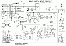
Thanks superjer2000, I saw some of your earlier posts and they were very helpful. My latest update: my IIci is sort of working. I decided to go one machine at a time, put aside the IIsi for the moment, and try to debug the IIci startup circuit using this schematic:

imageproxy.gif

This machine was recapped a few years ago, so in theory there shouldn't be any startup circuit problems, but I spent a few hours with a scope examining the behavior at various points and trying to understand the circuit's operation. Eventually I found that R112 (or the traces connected to it) seemed broken. According to the schematic it should be 15K ohm but I measured a resistance around 100 megaohms. That resistor is a pull-up for the asynchronous clear input of the 'HC74, so without it I think the bottom "turn off" circuit might engage unexpectedly. I touched a 10K resistor between that pin and +5V while booting, and suddenly it worked! The machine turned on and stayed on. Soft power-off worked too.

The bizarre thing is that after removing the 10K resistor, the IIci still works fine. ???!! So I'm not sure that was even the problem, or whether I should make the change permanent.


bigmessowires

Well-known member
Confirmed that R112 was the problem with the IIci. After manually adding and removing a replacement resistor, the IIci would work for a few more on/off cycles, but would eventually stop working again. Confirmed that the trace between R112 and UB13 pin 1 was bad, and patched it with a jumper wire. All seems OK now, but I'll keep testing. I have to decide whether to keep the original PSU, which was likely fine after all, or spend more time mucking with the ATX replacement.

Now for part two, the IIsi that's exhibiting the same symptom of turning off immediately after turning on. From a quick glance at the logic board, the IIsi uses a different startup circuit than the IIci, and I couldn't readily identify which parts are involved in startup. I haven't found any IIsi startup schematics either, so I'm not sure where to begin troubleshooting this one. It was recapped a few years ago, but dripping goo from the PSU may have eaten away traces on the logic board. I tried cleaning everything with alcohol, but it didn't change the behavior. I'll welcome any suggestions on where to start with troubleshooting the IIsi startup.


superjer2000

Well-known member
Glad you got the IIci working.  What I was getting at above is that the electrolytic goo continues to eat away at the board unless you've been able to fully clean it off / neutralize it.  I had probably about 4 or 5 patch wires on my IIci to get my soft power working again.  I'm not sure if all of the chips I replaced were bad, but it gave me a chance to do a better job of cleaning underneath them once removed.

I would have guessed that your IIsi's PSU is bad as the caps in those do give out, but if you're confident that your ATX PSU and soft power mod works fine (does it work with the IIci now that you have fixed those traces?) and you're seeing the same symptoms on your IIsi when using the ATX supply then it might be another eaten trace.  I was lucky with my IIsi as I just needed a regular recap and a replacement PSU.

I'm sure some of the boards I recapped initially will continue to develop problems down the road.  I now clean my boards with distilled water and baking soda after removing the old caps.  I don't know if that's the right way to do it, but that's what some of the forums said to use to neutralize the capacitor goo.


bigmessowires

Well-known member
Yes, the IIci works reliably now after adding my patch wire, using the ATX PSU and soft power mod.

I spent a long time with the IIsi logic board and a scope, but I couldn't figure out exactly what's wrong with that board and why it turns itself off. However, I'm suspicious that the "soft power mod" doesn't work correctly with the IIsi. What I found was that the IIsi power button is wired directly to the 68HC05 microcontroller on the logic board. Pushing the button grounds an input pin. Then another 68HC05 output pin is wired directly to the /PFW pin on the PSU connector. There are probably other capacitors and components in parallel with these, but I'm certain of these two connections. The 68HC05 is powered from 5V standby power, so it's always on.

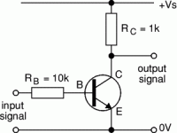
When the power key or power button is pushed, I observed that /PFW goes high for about 700ms. And when a shutdown is requested through software or the power button is pushed a 2nd time, I observed that /PFW goes low for about 50ms. That all seems good. But when the IIsi is steady-state on, it looks like /PFW just floats, or is somehow driven to an intermediate value around 1-2 volts. That's bad, and it screws up my soft power mod, which is basically just your single-transistor inverter from another thread:

imageproxy (1).gif

The only difference is that I used a MOSFET instead of a BJT, so there's no resistor on the base. I tried it with and without a pulldown resistor for the base (or the gate in the case of MOSFET).

If you look at the IIci startup circuit schematic, the symptom I'm seeing could be perfectly explained if diode D6 were missing. That diode holds /PFW high once the main 5V supply is on, even after the startup pulse generated by UE13 is over. But on my IIsi there doesn't seem to be any equivalent to D6, or it's broken, or maybe it's actually located inside the IIsi power supply instead of on the logic board. 

I tried adding my own external diode to serve the same purpose. It sort of worked: the IIsi would turn on from soft power, and stay on, but when I tried to turn it off, it would turn back on again after a half second. The observed voltage for /PFW also didn't make sense for what I thought I understood about the circuit. It was too low, as if the 68HC05 or something else were actively pulling it low, but only weakly. I gave up at that point, and concluded I just don't understand how this is supposed to work.

So in the end, I'm still not sure if my original problem was in the IIsi logic board, or in the IIsi power supply and further compounded by a flaw in my soft power mod with the ATX power supply. 

 
Last edited by a moderator:

bigmessowires

Well-known member
I tried replacing my soft power mod with your circuit exactly: an NPN BJT with 1K pullup and 10K base resistor. The startup from soft power works reliably, but it won't turn off. Here's what I observe on the /PFW signal from the logic board, when I try to shut down:

shutdown.png

The /PFW signal starts at roughly 2.7V (I don't know why this strange value). Then it goes to 0V for 50 milliseconds, but I think this pulse may be too brief to fully shutdown the ATX supply. After the 50 ms pulse, the voltage jumps up to 1.3V, slowly decays to 0.1V, slowly grows to about 2.9V, then jumps back up to 2.7V.

Then I tried adding an additional 10K pulldown resistor for the input signal, and this seems to work. The shape of the /PFW waveform is the same as before, but the overall voltage levels are slightly lower due to the pulldown. This prevents the voltage from creeping back up to the point where the transistor turns back on after shutdown, so it turns off and stays off:

shutdown2.png

So I guess that's success. :)  But I still don't understand why the BJT behaves differently from the FET, or why the voltage creeps up again after shutdown, or why the voltage is a weird value like 2.7V instead of a valid logic value. But assuming this is normal behavior (?), the good news is my IIsi logic board is OK and it's the PSU that I need to address. So I can either recap it and hope that fixes everything, or replace it with a micro ATX supply inside the case, or use it with a standard ATX supply outside the case like I'm doing now.


dougg3

Well-known member
I did some digging on schematics, and the IIsi logic board has a resistor in series with a diode going from /PFW to 5V similar to the IIci. On the IIsi: R115 is a 3.3k resistor that should be connected to /PFW on one end, and D3 on the other end. D3 goes to 5V. Might be worth a check...


superjer2000

Well-known member
There must be an issue with the IIsi logic board. I'm running the same ATX power supply and same soft power mod in both my IIci and IIsi with no difference in behaviour (ie they both power up and down perfectly reliably).  Good luck!!


bigmessowires

Well-known member
Thanks, that's good to know, even if it's a little discouraging. And Doug, I was able to verify everything you mentioned: the traces connecting R115 and D3 to the rest of the system are OK, and D3 checks out fine with my multimeter's diode test mode. 

With the BJT inverter, the 3.3K resistor R115 will be in series with the 10K resistor on the transistor base. Combined with the diode drops from D3 and from the transistor, my math says it should be 3.45V at the point between the two resistors where I was measuring. That's higher than the 2.7V I saw, but not wildly off.

But I did some earlier tests with a FET, where there should have been virtually zero current flowing through R115, so the measured voltage should have been 4.4V after the diode drop. I didn't save those graphs, but the actual voltage I measured was around 1.8 to 2.5V. Maybe I should repeat that test.

The big question is why /PFW shows that odd behavior after the 50ms low pulse, where it decays down to nearly zero, but then slowly increases again. There must be more RC components in this circuit somewhere that are effecting its behavior. 


bigmessowires

Well-known member
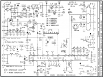
Ahh, some logic board schematics are in this collection here:


The relevant part for the Mac IIsi startup circuitry is on the page with the ADB stuff:

iisi-ADB.pngI

I see D3 and R115 that Doug mentioned, at the lower-left. But I also see some crazy stuff... the 68HC05 doesn't appear to be powered by 5V standby power as I thought (pin 10 on the PSU connector). The schematic shows a supply symbol that's a triangle with three lines inside subdividing it. And it looks like that funny triangle supply is derived either from the battery, the 5V standby (labeled "power monitor line" here), or from the 12V supply. The 12V supply path at upper-left is the weirdest part. 12V goes through the parallel resistors R172 and R173, then through a couple of diodes to the funny triangle supply and the main 5V supply. I don't understand what's happening there.

No matter which path powers the funny triangle supply, it has a resistor in series, if I'm reading this correctly. Why would you ever put a resistor in series with your supply? That would mean the 68HC05 could only draw a tiny amount of current.


dougg3

Well-known member
Yeah, I'm not sure where I originally got them, but those are the same schematics I was looking at. This must have been around the time Apple was transitioning to using the CUDA chip for power control. I think it's in control of the PRAM, so that's probably why the battery can power it too...maybe limiting current to minimize battery draw? Dunno. Not sure why the 12V part of the supply is involved at all. Well, darn. I was hoping it was going to be as simple as that diode having a problem.


bigmessowires

Well-known member
Probably the 68HC05 wasn't intended to draw more than microamps when the Mac is off, so the series resistors don't really matter. I think I understand the 12V part now - it's basically a simple 5V regulator. So once the PSU turns on and the +12V supply is live, the 68HC05 can draw as much current as it wants (up to about 13 mA by my math).

I've poked and prodded this thing 100 different ways, and my conclusion is that something not shown is pulling PFW towards the wrong values. When it should be about 4.4V (pulled up by D3 and R115), I instead see lower numbers like 1.4V or 2.7V. And when it should be 0 after a shutdown, I see it growing up after the shutdown, from 0 to around 1.0V.

Two possible explanations:

1. Weakly conductive goo on the logic board has created a weak short-circuit between PFW and some other trace.

2. The 68HC05 output pin for PFW is damaged: when it should be Hi-Z it's actually weakly driving some value about 1 to 2 volts. 

I'm planning to recap the original PSU from this IIsi, and just hope that everything works. If it doesn't, I'll try replacing R115 with a smaller value resistor like 1K. That should pull up harder against whatever is pulling PFW down during startup. If that still doesn't work, I'll just jumper PFW to 5V standby so the Mac will turn on whenever it's plugged in, and to hell with soft power. :)  


Bolle

Well-known member
Did you try desoldering the 68HC05, cleaning everything and putting it back on?

Those things have super sensitive inputs as it seems and tend to get whacked out once the slightest corrosion is setting down on one of the pins.

Have been doing this on a lot of CC boards that wouldn’t power on and they magically sprung back to life.

Also make sure all pullups on any pins of the 68HC05 are actually connected and no traces are broken.

 
Top