• Updated 2023-07-12: Hello, Guest! Welcome back, and be sure to check out this follow-up post about our outage a week or so ago.

M5126 Macintosh Portable Sad Mac (0x14/0xCD36)

SuperSVGA

Well-known member
The board is on the table with only the battery connected to one side of the molex connector. Does the 6V battery need to connect to both positives in that connector?
Yes, it needs to be connected to both positive pins otherwise things like the 1.2V reference, negative voltage generator, and some signaling will not get power. You should then see the battery voltage on the blue highlighted pin in the earlier image.
 

sgervasi

Member
Here's the results with all 4 pins on J17 connected to the battery and with the power supply connected:
Right after I reconnected the battery I read 1.22V on the comparator green pin, .06V on the red pin, 7.51V on the yellow, and the blue pin now reads battery voltage at 6.45V
the op amp to the left then showed green 1.22V, red 1.49V, yellow 0V. I then was able to get the short squeal from the speaker, and a sad mac on the screen but not every time. I could unplug the charger maybe hit reset and sad mac would show and disappear - maybe unplug the battery, plug it back in, hit reset, then press space bar and sad mac would show up again! Crazy

Today after the board was plugged in for awhile I noticed the reference voltage on the comparator (green) reads 0.65V - the red is still 1.49, the yellow is 7.51V, and the blue pin still reads 6.45V.

Seems like something is degrading
 

Berenod

Well-known member
Here's the results with all 4 pins on J17 connected to the battery and with the power supply connected:
Right after I reconnected the battery I read 1.22V on the comparator green pin, .06V on the red pin, 7.51V on the yellow, and the blue pin now reads battery voltage at 6.45V
the op amp to the left then showed green 1.22V, red 1.49V, yellow 0V. I then was able to get the short squeal from the speaker, and a sad mac on the screen but not every time. I could unplug the charger maybe hit reset and sad mac would show and disappear - maybe unplug the battery, plug it back in, hit reset, then press space bar and sad mac would show up again! Crazy

Today after the board was plugged in for awhile I noticed the reference voltage on the comparator (green) reads 0.65V - the red is still 1.49, the yellow is 7.51V, and the blue pin still reads 6.45V.

Seems like something is degrading
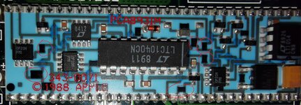
It might be the "painted" resistors.

On mine they are degrading, even after the mainboard got recapped and everything got thouroughly cleaned with ipa and distilled water.
The portable still boots, but is saying the battery is low, and then most of the times will shut off, eventhough voltage on all the pins of the power connector is close to 7 volts with the charger connected.
The resistors are those black "rectangles", usually with one or two tiny small scratches in it (done to reach exact resistance I assume).
Blow is the picture of the hybrid when I got the portable (and it was working perfectly, before the recap).
IMG_20220227_200856.jpg

After I recapped it, and super thoughly cleaned it, the hybrid kept deteriorating to the point where the rectangles are now sort of rounded...
I'll see if I can make a picture of the current state, then you'll see what I mean.

So, now I have one of the replacements made by Androda on the way (stuck in customs at the moment, almost here). That should fix it!
 

Berenod

Well-known member
I just want to know who thought painted resistors was a good idea.
I just wants to know which nerd expects a 30+ years old computer to work as it did when leaving the dealer (does not look into mirror :ROFLMAO: )

Seems those resistors are just fine right up till the caps start spilling their guts!

But yeah, can't ever recall coming across painted resistors anywhere else, so points for useless uniqueness!
 

3lectr1cPPC

Well-known member
Well, portables always had a reputation for being finicky and unreliable, before the caps started dying off. I’ll bet humidity gets them as well.
 

sgervasi

Member
The resistors look fine on this board - no damage, no degradation. It seems as though this hybrid board is bad but I certainly don't want to replace it without being sure. SuperSVGA has good knowledge but I know it's hard for him without seeing the board.
I know pin 8 is supposed to send voltage to the gate on Q16, but it's not for some reason. Q16 reads gate 0V, drain 7.42, and source 7.42 - which is strange because I think Q16 drain is supposed to send feedback to op2 to show enabled ram/ttl and 2nd stage mosfets so does that mean it thinks its on? I still can't figure out how 5 volts is non-existent on this board either, all I see is full charger voltage. Hope there's someone that can make sense of this :)
 

SuperSVGA

Well-known member
The resistors look fine on this board - no damage, no degradation. It seems as though this hybrid board is bad but I certainly don't want to replace it without being sure. SuperSVGA has good knowledge but I know it's hard for him without seeing the board.
I know pin 8 is supposed to send voltage to the gate on Q16, but it's not for some reason. Q16 reads gate 0V, drain 7.42, and source 7.42 - which is strange because I think Q16 drain is supposed to send feedback to op2 to show enabled ram/ttl and 2nd stage mosfets so does that mean it thinks its on? I still can't figure out how 5 volts is non-existent on this board either, all I see is full charger voltage. Hope there's someone that can make sense of this :)

You're seeing the full battery or charger voltage because the MOSFET isn't getting any voltage on the gate. At 0V it will just pass through the full voltage to the +5V. Normally you'll see around 2-4V on the gate, though it varies a bit.

Here's a simplified simulation if you want to see how it works. You can adjust the battery voltage and the 5V rail stays stable.

The always-on +5V rail is regulated by Q16.
Q16 is controlled by the output of the op amp.
In order for the op amp to run and properly control the voltage, it needs the following:
  • Power supplied to its V+ pin from the comparator.
  • The 1.2V reference.
  • Feedback from the +5V rail via a voltage divider.
With all three of those things and a working op amp, it should bring the +5V to the proper voltage. However it seems you're missing power and the reference in some cases.

The comparator uses the 1.2V reference against the battery voltage via a voltage divider to see if the battery is above 5.4V or so.
If the 1.2V reference isn't working or there isn't a proper reading coming from the battery, the comparator will not supply power to the op amp.

If you want to cheat and bypass the issue, you could run a wire from the comparator's V+ to the op amp's V+, and then from there run a 15k or higher resistor to the 1.2V reference to make sure everything is always powered.
 

sgervasi

Member
Thanks SuperSVGA - I'll try that bypass and let you know what happens. Let me make sure I have this right: I'm going to jump from comparator pin 18 (V+) to op2 pin 7 (V+) then through 15k or more resistor to comparitor pin 6 (reference V)
I guess Q16 is an enhancement-mode transistor?
 

sgervasi

Member
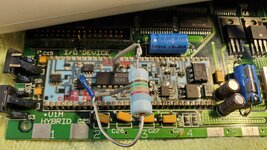
I did the bypass SuperSVGA gave above and the board now has 5.2 volts showing at Q16 drain like it is supposed to. The board still won't boot, but it does reliably get to a sad mac with error 03001500 00001FFA - no chime. V1M Hybrid bypass.jpg
 

alexGS

Well-known member
I did the bypass SuperSVGA gave above and the board now has 5.2 volts showing at Q16 drain like it is supposed to. The board still won't boot, but it does reliably get to a sad mac with error 03001500 00001FFA - no chime.
Love that resistor! Trust you’ve made a tidier job after you proved it worked ;)

Excellent detail from SuperSVGA in this thread about how the comparator and op-amp should regulate the 5V, and interesting measurements from you, which I shall use to diagnose my Portable that’s self-resetting when the floppy drive is used (and often taking several attempts to power up). I wish there was a way to ‘Like’ posts or ‘reputation points’ or something, to show my appreciation for this level of explanation. I was having a hard time trying to figure this out by myself.

Did you solve the Sad Mac error? - sounds similar to the 03001300 00001FFA that I have (on my other Portable) - the NMI line (Interrupt button) seems to have insufficient pulling-up and floats around 2.8V. But I don’t yet know if this is the problem - I wondered whether your error code was caused by something similar.
 
Last edited:
Top