-
Updated 2023-07-12: Hello, Guest! Welcome back, and be sure to check out this follow-up post about our outage a week or so ago.
You are using an out of date browser. It may not display this or other websites correctly.
You should upgrade or use an alternative browser.
You should upgrade or use an alternative browser.
Laser 128ex....how to revive
- Thread starter OleLila
- Start date
OleLila
Well-known member
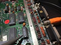
On U34, pin 10 and pin 3 both read as steady 5 volts. I DO NOT have keyboard or internal floppy disk drive connected because it will be much more difficult to access the board.
Even with magnifing glasses its difficult to hit the pins on MMU and then get a good look at oscilloscope, but not getting anything from MMU 64, 76,74,73.
Even with magnifing glasses its difficult to hit the pins on MMU and then get a good look at oscilloscope, but not getting anything from MMU 64, 76,74,73.
OleLila
Well-known member
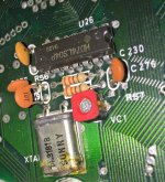
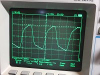
So the manual lists as part of U26, but XTAL1 looks pretty well labelled, big and silver just below U26 on the board and it gives me the only patterned oscillations I've found on the board, one pin a pretty smooth sin wave and the other regular and a little more stepped pattern......14.35 mhz on both pins, peak to peak voltage about 6 volts.
bibilit
Well-known member
Last edited by a moderator:
bibilit
Well-known member
Ok, think you have got something.
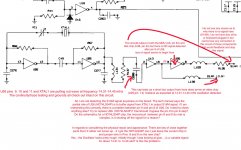
As SM14 is the master clock, and is lost, the Laser won't do anything.
U26 (74LS04) is a logic inverter, out of the 14 pins, where 7 is Ground and 14 is VCC (5 volts) the other pins are inverters ( 6 pair )
So if you input a Low signal at one pin, the output will be High, and the other way round...
https://electronzap.com/7404-ic-hex-inverter-not-gate-74hc04-74ls04/
I will not jumper or bypass anything for safety reasons, the chip is probably fried and cheap anyway, so you can cut legs of the old one to help the process of chip removal.
Concerning the nearby chip U13, if you have a look at Appendix D-7 concerning the external drive (this chip is related to drive failure)
As you had issues at the beginning with the external drive, this chip is probably bad as well and may had cause the failure of U26.
So i will replace both chips as a matter of fact, U13 is 74HCT244
Concerning the last question, you can probably tweak the crystal afterwards using VC1 (see your picture above) to the correct value.
Last edited by a moderator:
bibilit
Well-known member
According to Datasheet for the two chips, and if i am wrong anyone can correct me, this is what you should get :
Pin 1 of U13 should be Low (if not is OFF)
http://pdf.datasheetcatalog.com/datasheet/NXP_Semiconductors/74HC_HCT241_CNV.pdf
Then pin 2 and 18 are both Low or High (see logic table above)
On the U26, as you have two gates of a same inverter, if Pin 18 is High, then pin 9 of U26 will be High as well and pin 8 will be Low (and the other way round)
So, what feedback can you give me back on those ?
At some point you said a capacitor was shorted ? (C286)
Just my two cents, but i will more than happy to help you get your Laser working again.
OleLila
Well-known member
When I turn the machine on and measure first with voltmeter then with oscilloscope..........pin 1 of U13 shows no voltage and no frequency detected, at the same time PIN 2 of U13 shows 1.34 volts and frequency 14.35; PIN 8 of U13 shows 4.76 volts and no frequency detected, Pin 9 of U26 shows 14.35 frequency, PIN 8 of U26 shows nothing.
One time briefly (maybe over the course of 2 minutes) when I measured PIN 8 of U13, I got a 14.35 frequency however I quickly plugged in the screen (nothing on screen) and when I got back to measure other pins, it had reverted to the 3.74 volts again and all as above.
To be transparent, when I measure these pins, there is no doubt that as I put the probe on a particular pin and look to the oscilloscope, I have moved the probe and shorted between the pins. If this is ruinous then its all out the window....not much room for error at all and hard to imagine getting through all of these measurements, esp on the smaller chips, and not eventually getting between 2 pins.
I ordered replacement part for U13 (74HCT244) but received 74HCT244N which I did plug in and try but showed no change in activity.
So when I get a chance my plan is to go ahead a replace shorted C286 (68 pF) and crystal XTAL1.
Have to balance this with the day job and activity but hope to get to this in the next couple of days. Very much appreciate your looking bibilit.
Similar threads
- Replies
- 0
- Views
- 281
- Replies
- 42
- Views
- 3K
- Replies
- 17
- Views
- 1K

