• Updated 2023-07-12: Hello, Guest! Welcome back, and be sure to check out this follow-up post about our outage a week or so ago.

Issues with Mac SE/30 display (and more?)

Hi,

I recently got an SE/30 from and have been attempting to restore it.

When I first powered it on, it seemed to be working fine. Then, after maybe ~20 minutes, it crashed. After that, it would crash within a minute of starting up, and the display had all kinds of strange issues (mainly squiggles that would start wide at the top of the screen, and narrow towards the middle where they became a vertical line.

Now, when I start it up I just get a blank display, with a chirp and spinning fans, but no bong. One or twice, I got a quick flash, from the screen, and a few times there hasn't been a spinning fan. These seem to come and go at random.

So far, I've mainly  been following the Dead Mac Scrolls, supplemented with random guides and forum posts (I've basically been trying everything I can find).

I've replaced

  • the PRAM battery
  • R22
  • R19
  • CR2, CR3, CR5
  • Q2
  • Most of the electrolytic capacitors on the analog board (I just realized I'm missing c19, and I'm going to wait until I have a replacement before I do c22) 


I also resoldered all the connectors on the analog board, flyback transformer, and the coils, and generally cleaned the boards (although half the solder joints on the logic board are corroded, I've not attempted to deal with this yet)

Based on the spinning fan and multimeter readings, the power supply seems to be working, but I don't know enough to say for sure.

Pictures as it is now:
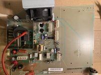
analog board.jpg

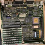
logic_board.jpg

My big concern now is that it may be the flyback transformer. They appear to be quite expensive, so I don't know if replacing is is an option, but certainly not if I'm not sure if its the cause.

Is there any way to test it? Is there anything else I can do, other than finishing the recap, and could the remaining capacitors affect the display like this?

I was also originally planning to recap the logic board, but when the display problem arose, I put it off. Could it (or the logic board problems more generally) be at fault? Any consensus on dealing with corroded solder? I've seen a lot of advice, but no single view on what approach is best. Once I get all the solder off, do I need to resolder each connection?

Any other general advice?

Thanks,

Neonachronism

 
Last edited by a moderator:
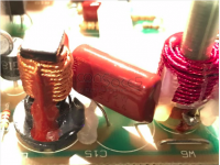
Hmm, I think that's on purpose: cap kit I got specified 


C15: 3.9uF non-polar low-ESR electrolytic will be replaced by a large red film cap.
Could this be a problem?

I can try it the other way (it didn't indicate how it should be installed).

Edit: No change with it flipped - click, spinning fan, no display.


Last edited by a moderator:

Michael_b

Well-known member
Hmm, I think that's on purpose: cap kit I got specified 


Could this be a problem?

I can try it the other way (it didn't indicate how it should be installed).

Edit: No change with it flipped - click, spinning fan, no display.
I would expect a large red film cap to look like the attached - in fact I grabbed that image from the cap kit you linked. 

Are you sure you didn't actually install the cap intended for C15 into the C12 spot? The original C12 cap is a film capacitor, so I think it would be an easy mistake to make. Also your C12 looks oversized relative to what I have on my analog boards. There's really not a good reason to replace C12; it's not electrolytic so it's not plagued by leakage as the other caps are. 

C15 on the other hand is electrolytic on the stock board - however, finding the correct value non-polar electrolytic is difficult/expensive, so the film capacitor is a common swap (though film capacitors aren't exactly cheap). 

If you have a polar cap in there, it's going to be wrong no matter what direction you've got it, AFAIK. If it is the flyback (don't ask me, I don't know), you might find this to be of interest.

Screen Shot 2020-06-28 at 8.37.25 PM.png

 
That makes a lot of sense - I was a little confused why there was what looked like a ceramic capacitor mixed in.

Thank you very much! 

Oh, and thanks for the pointer to the spare boards - I'll probably pick one up just for spares.


davidg5678

Well-known member
All of the electrolytic capacitors on the logic board leak over time and cause corrosion which can result in video problems, among other things. These need to be removed and replaced with new ones. It is possible that some of the things you read about in the Dead Mac Scrolls are also true, but many issues are caused by these capacitors, which were not as big a problem the book was written. It is important to replace the capacitors on the logic board as an initial troubleshooting step, because there is a near guarantee that they are not working as they should.

I also think moving the capacitor on your analog board is an important thing to do, as I also remember placing my capacitor in another location when I recapped it.

These videos explain how to properly recap a Mac SE/30 Analog board and how to recap logic boards, so you may find them useful resources if you haven't seen them already.

Good luck!


Thanks for the info! I was always planning to recap both boards, but I was going to wait to do the logic board until I had video. I guess I'll move it up the priority list (although still I have to do some more practicing first). Hmm, and I guess I should do the power supply too.

I finished the AB recap. I did have to use a wire to extend the leg of the real c15 (I've ordered a replacement too).

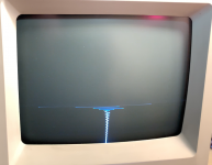
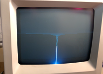
Now, about 2/3rds of the time, its starts with a chirp, no HD light,  and sparking sounds, sometimes with flashing on the display, often like this:

Screen Shot 2020-06-29 at 8.59.58 PM.png

Screen Shot 2020-06-29 at 9.00.19 PM.png

Note that the red on the top right is a reflection of a lamp. These are very similar to what I saw right before the display stopped lighting up. According to the Dead Mac Scrolls, this could be related to c15, so maybe my little leg extension is causing an issue? (Most of my electronics experience is in digital logic, so this analog stuff all seems like voodoo : ). I've already done their other fixes for the horizontal sweep (r19 and resoldering P1 and L2), so I'm a little stumped. It seems like it's more likely to happen if I unsolder a component to test it, and resolder it (making no "fixes"), so I wonder if there's a loose connection somewhere.

Once or twice, I've gotten a raster for a split second, with a classic simasimac.

I've never seen anything like this is the books or the internet, so I'm not really sure where to go from here. I'm expecting the new AB near the end of the week, so I guess I'll try transferring the the flyback transformer to my board (or should I try the other AB first, in case it works [but considering it hasn't been recapped]?).

Anything else to try in the meantime?

And once again, I really appreciate the help.

 
I tried resoldering P1 again; it didn't seem to help. 

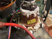
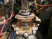
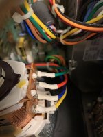
Here are some pictures of the yoke - anything look out of place?

2020-06-30 10.35.19.jpg

2020-06-30 10.35.27.jpg

2020-06-30 10.35.35.jpg

I only cleaned the yoke with air, out of fear of damaging any coating that might be on the windings, but I do also have contact cleaner - might that help?

If the yoke is truly damaged beyond repair (at my skill level - relative beginner, if it wasn't clear), I take it my only option is to buy a complete monitor? 

 
Last edited by a moderator:

davidg5678

Well-known member
Are you able to verify the voltages produced by your power supply are correct? I think I once saw a similar pattern on screen when a computer had a faulty power supply.

 
I've been checking at the external floppy port, and I usually get a very steady readings close to 5v (just now, it was 4.98v). Once or twice, the fan wouldn't spin, and I got reading closer to ~2.25v. When that happened, I usually pulled one of CR2/CR3/Q2/R22/R19 to test them, and when I put them back it went away. 


davidg5678

Well-known member
I've been checking at the external floppy port, and I usually get a very steady readings close to 5v (just now, it was 4.98v). Once or twice, the fan wouldn't spin, and I got reading closer to ~2.25v. When that happened, I usually pulled one of CR2/CR3/Q2/R22/R19 to test them, and when I put them back it went away. 
Hmm... I think this may indicate that you have a failing power supply. It likely also needs to be recapped or replaced with a modern alternative.

I found the video where I previously saw a similar-looking issue: If you take a look at the beginning of this video (about 50 seconds in), I think the issue the computer in the video has is similar to yours (at least as far as I can tell from your photos and descriptions). There is the same loss of horizontal deflection/lightning bolt pattern on the CRT. (The video below is about replacing the PSU entirely, but if you'd rather recap yours, the same channel has another video about that too.)


Good find, thanks! I'll recap it, and if that doesn't do it, replace it.

At this point I've looked at bits and pieces of this guy's videos, but it seems like I really need to watch them through.

 
I recapped the power supply, and with a bit of adjustment, got 5.01v and 11.93v. 

9/10 startups, I get nothing, but once after ~10 seconds, I get a raster for a second or two (with a mouse cursor!), followed by the zigzag pattern. No bong regardless. 

I guess the option of replacing the power supply with a modern one is still on the table, though I don't know if I'm quite ready for that - they seem a little expensive, and I don't know if I have the skill set to choose an appropriate one (the ones others have used tend to not be available). 

In case the issue is the yoke, I ordered a new CRT from the same seller Michael_b posted. At the time, I thought I remembered that the CRTs were all compatible across compact macs, but more recently, I came across some material that indicates that while the CRTs are all compatable, the yokes are not, and generally the yokes are kept across CRT replacements. 

Once I receive the CRT, is there any easy way to tell if the yokes are compatible?

I take it that switching the CRTs but keeping the yoke wouldn't help if the yoke truly is dead. I actually wouldn't mind swapping the CRT anyway, since mine has a dead spot in the center, but the yoke seems pretty complicated and I'm not sure I want to risk breaking it further for a single dead pixel.

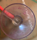
I finally received my analog board. At this point, I would try swapping out the T2 (other than that, I think I've run out of things to replace), but unfortunately, the clip on the anode is missing:

Screen_Shot_2020-07-05_at_2_34.54_PM.png

I'm kinda stumped on this one. If I really thought the T2 was the problem, I would just splice my broken T2's cable on to this one, but I don't want to do that and risk breaking a good transformer for a bad one. I guess if I could get the cap off the wire, I could right up some kind of clip, but this seems like the kind of thing that shouldn't be jury-rigged, what with the high voltage and all.

Any thoughts/suggestions? 

Thanks again, everyone!

 
Last edited by a moderator:
Top