• Updated 2023-07-12: Hello, Guest! Welcome back, and be sure to check out this follow-up post about our outage a week or so ago.

Idea: Macintosh Classic III (LC550+M1420)

mg.man

Well-known member
What about using the FPU "slot" (and guides for support) for a 4 SIMM "SIMM saver" turned 90°? FYI, I brought a bunch of dual / angled 30pin PCB SIMM holders (metal clip) a la the SE ones back from the US for @max1zzz. If those were used with 16Mb SIMMs, that'd get you to 64Mb... 🤔
 

max1zzz

Well-known member
What about using the FPU "slot" (and guides for support) for a 4 SIMM "SIMM saver" turned 90°? FYI, I brought a bunch of dual / angled 30pin PCB SIMM holders (metal clip) a la the SE ones back from the US for @max1zzz. If those were used with 16Mb SIMMs, that'd get you to 64Mb... 🤔
IIRC the memory controller of the CII dosen't allow for more than 10MB (It just a modified LCII "V8" so shares this limitation with the LCII)

nvm, didn't realise we where talking about the modified board here

In theory moveing the memory to a riser should be possible, I am however kind of inclined to just solder 64 or 128mb of memory direct to the board and do away with the slot compleatley
 

mg.man

Well-known member
I am however kind of inclined to just solder 64 or 128mb of memory direct to the board
I guess it depends on the price-point you're aiming at... what about 16M (or maybe 64M on the 'board and a expansion slot card for additional?
 

Trash80toHP_Mini

NIGHT STALKER
Memory on the logic board itself defeats the purpose if it doesn't fill a bank to its maximum capacity as max is suggesting. Empty SIMM Slots cost a lot less than memory and leave the final loadout to the builder. Apple's "built in memory" is a by design bottleneck to expansion capability. You won't find it hamstringing any high end system I can think of offhand. Designed in limitations to "protect the high end" are everywhere to be found, but that's my take on it, others think in terms of average users who may never upgrade their systems.

CPU/Ports Logic Board with a slotted Memory System/PDS Riser Card seems the only way to expand on the Classic's ridiculous form factor. Tiny logic board mounted in a mezzanine position to minimize cubic for processor upgrades topside and tons of empty cubic underneath? Bad on you Apple, very very bad. :cautious:

You find all kinds of SIMM Savers available and riser card slots for CPU and PCI Slots for PPC systems, especiall in the far more creative Clone designs. One Clone system had PCI AND NuBus slots on a riser for it, PowerComputing? Lets pull some of that flexibility back into the 68K lineup? @max1zzz whatcha thinking now?

I really like the Memory/PDS Riser concept as it will allow for experimentation in assessing the absolute limits of memory, RAM, VRAM, ROM and will break even something as simple as an LC NIC out from under the hood , further allowing something like the LCIII adapter for 50MHz P33 PowerCache. That doesn't use the LC's $E PDS interrupt, so a NIC/whatever can be used in tandem with the Accelerator on a riser designed for it.

I'll have to play a bit with this in Illustrator. :)
 
Last edited:

dcr

Well-known member
If you're using an LCIII board (original or redesigned), wouldn't it also be feasible to use a color LCD @640x480 (if you can find one) and basically have a Macintosh Color Classic III?
 

Trash80toHP_Mini

NIGHT STALKER
Yep! But would require case mod. Folks were looking for simple after I bounced more aggressive approaches off the wall here. So I did my best to come up with something fairly simple to fit the case without modifications while increasing expansion capability of the original LCIII design max has reversed..
 

max1zzz

Well-known member
@max1zzz whatcha thinking now?
Well i'm still kinda mixed, I would prefer slots but SIMM sockets can be somewhat hard to find (At least in the UK thy are, they are somewhat easyier to get in the US but that means buying through a proxy for me...)

Though thinking about it a riser card could give the best of both worlds as it can either have slots on it or could just have the DRAM soldered to it if the supply of SIMM slots dries up :)
 

Trash80toHP_Mini

NIGHT STALKER
I was thinking about your RAM ICs on the LCIII memory riser for this feasibility study. There'll be room at the base of the card for SMT RAM on both sides of the riser at the transition from slot in the basement to above deck where SIMM slots can then be located.

Depending on the maximum addressable RAM in Bank A, it might be a good idea to reserve those strips of PCB acreage for doing that if possible? Even putting pads for something as little as 16MB in Bank A as a fallback position would be a great start if someone would like to go that way? Gotta bone up on the LCIII DevNotes and compare its memory controller implementation to other systems using it for clues about where this could lead.

Definitely want to see provision for a pair of VRAM SIMMs . . . just to see . . . 😬

Dunno, having the entirety of the memory subsystem and PDS implemented on a riser will afford a tremendous amount of flexibility for future projects. I'm thinking in terms of adding an "upright slot" on the vertical riser that would be a PowerCache adapter. It would be located just below the RA PDS connector atop the board to lay NIC or other interrupt requiring card horizontally atop the Accelerator in its connector, both parallel to the deck.

Gotta play with the riser concept in AI so I can post .PDF images of the boards. That way anyone can mount printouts to cardboard for cutout and installation in a chassis to get a 3D feel for where we're going if they'd like.

Suggestions more than welcome, we're at the spitballin' stage here gang. :)
 
Last edited:

Trash80toHP_Mini

NIGHT STALKER
Interesting, does the LCIII have sleep mode? That'd be like the Powerbook 100.

And if going that route, open up possibilities re. chip densities...
Take it further? I've always wondered about voltage leveling for running more modern 3.3V ICs or higher capacity modules? Memory/PDS Riser setup allows for all kinds of prototyping on both fronts. PCB size and footprint of board is flexible if limited for running inside the bucket, but risers ca be oversize for running a large prototyping system. The CPU/Ports board need never be removed for access to the two subsystems on the riser.
 

alectrona2988

Well-known member
What I'm curious about is if we could do something like this: https://www.retrorgb.com/reverse-engineered-game-gear-motherboard.html
What was done consisted of reverse engineering the board (and the chips if I'm correct!) and further streamlining the components. Not sure if it's doable, but it could potentially be easier.

I also want to stay in the realm of 68k, maybe old world PowerPC. It gives the project more charm, and won't end up like an iPad screen with a Raspberry Pi in it. Don't get me wrong, those projects are nice if the computer is broken, but I would love to see if I could preserve as much of the original components as possible... except the board. Also, as I was writing this... maybe adapting the SE/30 design and streamlining it to be more akin to the Classic II would be a good idea.
 
Last edited:

Trash80toHP_Mini

NIGHT STALKER
... maybe adapting the SE/30 design and streamlining it to be more akin to the Classic II would be a good idea.
You're on the right track, but lack of LCIII built in video subsystem would be the problem you'd face.

IIsi in SE/30 form factor is being looked into however. That improve upon SE/30 performance and expansion capability via NuBus adaptation. You got me wondering about that in Classic, but I'll shut that down right off the bat.

LCIII boards are faster right off the starting line and the cost of a NIC is negligible as opposed to very costly. There were/are more units shipped/available at lower cost. So I'd think many more would have been destroyed in the Maxell bombing campaign and from other causes. Re-purposing of known good boards isn't something we'd want to encourage.
 

alectrona2988

Well-known member
Ahhh, gotcha. The LC III sounds like a better idea after all. Just thought about the SE/30 already having a monochrome video output and such...
 

Trash80toHP_Mini

NIGHT STALKER
Suggestions are always in order, as they say: the only stupid question is the one that doesn't get asked. You probably wouldn't believe how ridiculous some of my notions have been. But some that appeared outlandish at first have worked out very nicely. ;)
 

Trash80toHP_Mini

NIGHT STALKER
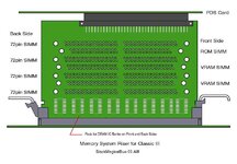
Knocked together my first AI doodle for posting in quite some time now:
BlackMagicalBus-Classic-III.jpg

I'm sure we won't need FOUR 72pin SIMMS, but you never know. I'm hoping a pair of 512K VRAM SIMMs can be addressed by the LCIII board, but I doubt it? Faked up the DRAM IC Pads and right angle PDS Slot is based on measurements, but it's late, hope you get the idea. :sleep:
 

alectrona2988

Well-known member
So we're adding in a PDS slot? That's something I didn't expect with this project. I wonder if one could probably even get the LC 475 design to work in a classic chassi.
 

Trash80toHP_Mini

NIGHT STALKER
Yep, that's in the spec. for my feasibility study. I mentioned it in .TXT upthread, but my descriptions leave a LOT to be desired.*****

One day it might be a workable project to reverse engineer boards with more than four layers, but not at present without employing the "mill layers away and scan process." @max1zzz had already done the LCIII and is bringing a prototype to life. But his four layer LCIII board was developed in ____?____ which doesn't lend itself to mooshing components around. So the LCIII in SE/Plus project has been moving into KiCAD as will this project as well, if and when.

Back to your Classic III proposal: The rotated J and inverted U approximate interference of the chassis opening lips with the locking tabs of the DIMM socket. I need to source some vertical SIMM sockets for playtime.

Don't know If I can work things out within constraints as is, but going a tad Rube Goldberg would be one option. A more KISS principle compliant solution would be implementing a two layer Ports breakout board in the Classic form factor with picture frame opening. The CPU board would then be bolted up/connected in the RPi hat manner from below.

The Memory/PDS riser would become an inverted T form factor _|___|_ installed before CPU board would be mated to the simple ports board. Not optimal costwise, but what part of this clever endeavor would be inexpensive? :)

If you can make sense of the above .TXT, good on ya! Iterative AI doodles done, printed and installation photo sessions will be needed. ;)


***** Many years ago @Bunsen pointed out the problem with my textual descriptions. So I switched to illustrations in AI and was told that they helped get the images in my noggin across much better. Here's a not ready for prime time, block diagram teaser for another LCIII adaptation proposal. Could never get this one across in words. Black Box development would of the Eleanor class on this front:


That's a case in point, tangential discussion of that proposal in this thread discouraged. Research for dedicated topic in progress.
 
Last edited:
Top