• Updated 2023-07-12: Hello, Guest! Welcome back, and be sure to check out this follow-up post about our outage a week or so ago.

Help with 475 missing pads

Doug_M

Member
Hi,

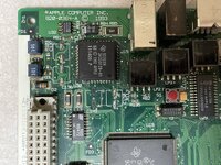
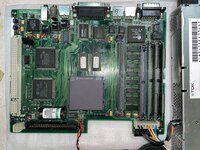
I have a Performa 475 logic board that I am re-capping. First time working with surface mount components and you guessed it, I ripped off a few pads. I swear I wasn't using the "twist" method 😄 but 4 pads ripped off anyway.

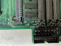
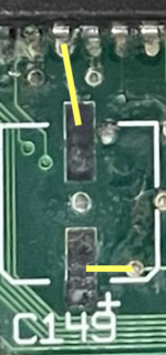
So I need to run some bodge wires I suppose but I don't know where from. Here are the missing pads:

C149Both + and - pads
C101+ pad
C128- pad
 

mg.man

Well-known member
The pads came off because you didn't use the twist method.
At the risk of opening the debate...
^ what he said

Maybe I have refined my technique, but I've probably recapped 3 or 4 dozen 'boards during the COVID years and only ripped off a 1/2 dozen or so pads using the 'twist-method'... When I do need to repair these, I use a short piece of wire-wrap wire to go from the trace to under the cap pad.

Post some pics of the damaged area and I'm sure the community can help you figure out where the repairs need to connect to.
 

joshc

Well-known member
1676230542230.png

Can't see C101 in your photos.

C128 - probably goes to the other side of the board but I would need to check my 475 to be sure.

You have more to worry about than missing pads though - that board is very dirty, especially around the DFAC area.
 

Doug_M

Member
Thanks Josh, much appreciated.

Currently I only have q-tips and 99% pure isopropyl alcohol for cleaning. What do you (or anyone) recommend for cleaning? One of those fibre-glass pencils perhaps?
 

joshc

Well-known member
Currently I only have q-tips and 99% pure isopropyl alcohol for cleaning. What do you (or anyone) recommend for cleaning? One of those fibre-glass pencils perhaps?
Small dental brushes or a toothbrush work well on IC legs too.
Failing that, when the dirt is really ingrained and the pads look like yours, I use a hot air station to remove chips, clean the pads with new solder/wick and then solder everything back.
 

zdw

Member
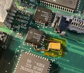
I had a similar problem with C35 on a system I was recapping, where removing it pulled off both pads and the power vias. Only happened on this cap, none of the others.

I looked up datasheets for the nearby serial transceiver chip, and attached the replacement cap to that instead with magnet wire - the power and ground pins are next to unused pins, so they're easy to solder to. IMG_3273.jpeg
 

Doug_M

Member
UPDATE:

My friend helped me with soldering the bodge wire to the chip for C149. He couldn't solder to the dot (what is its proper name?) to the right of the missing solder pad (more on that) so he soldered to the positive of C150. Is that correct? Visually it looks correct to me, but positive to positive doesn't seem right. Back to the "dot". He didn't want to scrape. I think I "dirtied" it in my prior attempts and should be able to scrape/expose it.

Also, I would like to test the voltages of each tantalum capacitor but I don't know what they are supposed to be. Does anyone have a list or could measure them for me? I would greatly appreciate that. I've numbered them in the image below for reference.

Thanks,
Doug

IMG_0202.jpeg
 

zdw

Member
Also, I would like to test the voltages of each tantalum capacitor but I don't know what they are supposed to be. Does anyone have a list or could measure them for me? I would greatly appreciate that. I've numbered them in the image below for reference.
All of the pins on the capacitors are tied to the power pins - I would unplug the PSU and use a multimeter to tone them out (continuity check) from the power supply pins from the side with the wider line on it (which is positive in almost all cases) to the corresponding pin, and from the other side to the ground pin.

From memory, the positive sides of each capacitor:

1 and 2 are a 12v and 5v to the hard disk
3, 4, 5, 6, 11 should be 5v
7, 8.9,10 are a mix of 5v and -5v (which the positive pin is to ground)
 

Doug_M

Member
Okay, the multi-meter with continuity test I ordered arrived and I've had a chance to check the caps. All are good except C127 negative side. I de-soldered it and checked the pad. No continuity. So a bodge wire is needed.

C127 neg side (closest to ram slot) goes to ground, correct? Could I just solder a bodge direct to the ground pin on the power supply header? If so does it matter which of the two ground pins I use?
 
Top