• Updated 2023-07-12: Hello, Guest! Welcome back, and be sure to check out this follow-up post about our outage a week or so ago.

ADB to M0100 mouse conversion

sfiera

Well-known member
I recently found a guide for ADB to M0100 mouse conversion [Japanese]. Here’s its schematic for the ADB Mouse II:
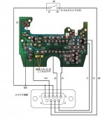
p1010738b4.jpg

Translations:

  • A, Bはどちらでも可: Either A/B is OK [orientation on the mouse switch doesn’t matter]
  • 基板上のJA, JBピンをはずす: Remove pins JA and JB from the original board [these are for the mouse switch, which you connect separately]
  • コネクタ端面: facing connector end [but I assume the pin numbering is a better guide]

Above the image, it notes that the red circles are direct connections, but the corresponding white circles are equivalent and easier for soldering.

Has anyone tried this sort of conversion? ADB mice are much easier to find, and I rather like the ADB II. It hadn’t occurred to me that you could to this, but it makes sense. Internally, I guess ADB mice still read the mouse ball with quadrature encoding, so if you bypass the chip, you get the M0100 protocol.


sfiera

Well-known member
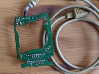
I got a DB-9 cable to try this, opened a M2706, and found—of course—that the internals are completely different from what’s described above:

MVIMG_20200718_115505.jpg

The instructions call for the button switch to be disconnected from the board, but that’s not possible here without cutting traces. I assume that the reason to disconnect the switch is because there would otherwise be two pull-up resistors on it, so I could desolder that resistor if I knew which one it was, but I think I’ll just open up a few more M2706es to see if I can find a match for the instructions.


sfiera

Well-known member
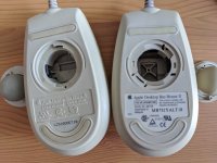
Actually, the reverse, I think:

MVIMG_20200718_122232.jpg

It’s hard to tell from the picture, but the rollers in the 1995 model on the left match the positions in the schematic, and the 1997 model on the right has them in the same position as the first PCB I looked at. It seems that the 1995 model is less PCB/more assembly, and the 1997 model is more PCB/less assembly, which makes sense.

I got out my soldering iron before realizing that I have a lot more work before I can put in the new cable: figuring out which wire colors correspond to which pins, figuring out a way to secure it in the case, etc.


cheesestraws

Well-known member
In case you would prefer to try it on something more expendable: It doesn’t need to be an ADB mouse specifically. Many many mice can be adapted like this, and ball mice in general are especially easy. The signal that goes over the wire on the M0100 is pretty much just the signals straight from the optical sensors around the ball. The same is true of mice that use a similar system, such as the Atari ST, Acorn Archimedes and (I believe) the Amiga. 

I am posting from my phone so can’t look up links easily right now, but useful key words are probably “adapt mouse to quadrature”


sfiera

Well-known member
Yeah. In Japan, NEC was making PC-98 bus mice up until 2000 or so. But, ADB mice are what I have (more than I need of) and I like the “right yet wrong”ness of plugging a Mac mouse into a Mac, except it’s an ADB mouse and a Plus.

Speaking of of “right yet wrong”, Apple even made a certain USB mouse with a ball, and it might be possible to adapt it in the same way…


cheesestraws

Well-known member
That's fair, just checking that you (and anyone who might find this thread afterwards) knew that your options were broader than just ADB mice :) .  Not meaning any reflection on what you want to do, of course. I definitely appreciate the "right yet wrong-ness" and it has occurred to me to do similar... 

 
Last edited by a moderator:

waynestewart

Well-known member
I got a DB-9 cable to try this, opened a M2706, and found—of course—that the internals are completely different from what’s described above:

View attachment 35618

The instructions call for the button switch to be disconnected from the board, but that’s not possible here without cutting traces. I assume that the reason to disconnect the switch is because there would otherwise be two pull-up resistors on it, so I could desolder that resistor if I knew which one it was, but I think I’ll just open up a few more M2706es to see if I can find a match for the instructions.
The conversion circuit board pictured is from a mouse with 1 screw holding it together. I poped open the half dozen I had handy and found 2 different circuit boards. Neither was the one pictured. Have more in storage but don't really have time to look for them ightnow

 
Top