• Updated 2023-07-12: Hello, Guest! Welcome back, and be sure to check out this follow-up post about our outage a week or so ago.

How many floppy drives can a SWIM chip control? (just curious)

sfiera

Well-known member
Would be neat to figure it out. Could potentially enable additional floppy drives, especially external drives for computers that don't have a floppy port on the rear.
Hmm. How many machines without a floppy port have two internal floppies? On single-floppy systems (say, a Q700), I’d assume that the /ENBL2 pin still exists, unused, on the SWIM chip. If you could tap into that, it would let you add a second floppy. Still no guarantee that ROM support for the extra floppy exists, but support for /ENBL2 seems more likely than that extra VIA bit.
 

olePigeon

Well-known member
Hmm. How many machines without a floppy port have two internal floppies? On single-floppy systems (say, a Q700), I’d assume that the /ENBL2 pin still exists, unused, on the SWIM chip. If you could tap into that, it would let you add a second floppy. Still no guarantee that ROM support for the extra floppy exists, but support for /ENBL2 seems more likely than that extra VIA bit.

Assuming the VIA bit and ROM issues are addressed, the Macintosh II, IIx, IIfx, and LC all have dual floppy and no external. The IIcx, IIci, IIsi, and SE/30 all have one internal and one external, and they're likely on /ENBL1 and /ENBL2, respectively. I don't recall if the LC II has dual internal still, or if they gave one up.

ROM support could be added via BMOW ROM and Plus ROM if it were possible to hack in support from the SE ROM. Theoretically also with the LC ROMs since they're already socketed.

I'm writing this like it's easy, but I know it's not. I'm ignorant of programming and reverse engineering, but I'm not ignorant to the work involved. You guys (and I mean all the hackers on here) are incredible and I'm extremely envious of your ability to do so.

In any event, I plan on heading to the surplus store this weekend to grab a couple DE19 connectors and some ribbon cable, plus some single pin connectors. I aim to make an internal-to-external cable that can be threaded through the lock slot. I found out our laser cutter is only 75w (probably close to 70w because it's an older, used unit), and I don't think it's strong enough to cut through 1/16" aluminum. So I don't think I'll be able to make a custom NuBus bracket. I'll find out when the technician gets here to set it up. We're waiting on maintenance to set up a 240v circuit.
 

LaPorta

Well-known member
I remember the diagram from the Macintosh Family Hardware book. It would appear that the ENBL1 signal/chain is a daisy chain of the same bus, but that ENBL2 is an entirely distinct pathway. That leads me to believe that, if I get the photo of the Mac Plus from the same book, that it would be ENBL1 for internal/ENBL2 for external. The separate GLU logic that takes place on ENBL1 probably was added to account for the two internal drives, and the ENBL2 pathway was carried over from the Plus.
 

olePigeon

Well-known member
@LaPorta @sfiera Hopefully ROM support has carried over from the Plus and SE, but even if it did, would it know to also daisy chain /ENBL2? It seems relatively straightforward. Assuming ROM support is there, you could borrow a GLU chip from a donor SE board, then perhaps clip into the VIA chip? Is that pin4 and pin5? Then hopefully enable daisy chaining on /ENBL2.

Edit: Or is it an additional, custom VIA chip just for daisy chaining like the extra GLU?
 

LaPorta

Well-known member
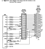
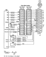
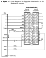
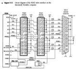
Here are competing diagrams of the Plus, II, Portable, and SE FDHD:

Screen Shot 2021-10-06 at 1.43.51 PM.png

Screen Shot 2021-10-06 at 1.44.29 PM.png

Screen Shot 2021-10-06 at 1.44.42 PM.png

Screen Shot 2021-10-06 at 1.46.11 PM.png


It looks like no matter what, ENBL2 is used for external (Except for the Mac II), and some sort of logic, somewhere, is processed for ENBL1 to switch it between the two internal drive ports. It appears to differ between model.
 

olePigeon

Well-known member
@LaPorta Hmm. My bitty brain sees it like this: I think three is the max no matter what without a second VIA (unless it has an additional pin that's not indicated in the layout ... perhaps in the chip schematic? If the schematic even exists outside of Apple.) Assuming the VIA in the Mac II can still parse the LO & HI, you could borrow a GLU chip from an SE and reroute /ENBL1 through PA4 & GLU on the Macintosh II. That would give you a 2nd drive on the first internal port (/ENBL1.) You could then run a jumper cable to the rear for the second port to create an external.

So I think it's still possible, just not on /ENBL2. You'd split /ENBL1 into two drives, and just leave /ENBL2 as-is. Assuming the VIA chip is still the same and PA4 is still used, and the GLU is the same in both the SE and FDHD (I hope so, SE is so much more common than FDHD), then it seems like it's possible.

But that's a lot of assumptions. Would love to try it out if I had a donor SE board.

Edit: Maybe it's the same GLU on the IIgs.
 

LaPorta

Well-known member
Oh yes, I’m sure that if you had the logic laid out right for ENBL1 and the chip, the rest seems pretty standard. I’m pretty sure they didn’t do it for the II because there was no good reason with two internal drives and all the NuBus slots that you could hook anything to. Saves cost when people are unlikely to buy a third floppy for such a machine.

Which reminds me, I don’t have the expertise to do this, but I have extra SE GLU chips if you wanted to try.
 

CC_333

Well-known member
Edit: Maybe it's the same GLU on the IIgs.
I'm not so sure about that. The IIgs is a hybrid 8/16 bit system, and the SE is a hybrid 16/24/32 bit system, so I kind of doubt they have much in common architecturally. Similar features, yes, but the implementations of such are likely to be completely different.

Perhaps one can study how the IIgs manages floppy drives, and how its GLU works (if it has one), and then come up with a plan to reverse engineer and re-implement any desired features (such as daisy-chaining support for the external floppy port) in a form compatible with the SE's architecture.

Another thing could be to look at how the HD20 works. It allows a form of daisy chaining, does it not? If someone could figure out what's going on there, maybe it can be re-implemented as a type of splitter that can allow multiple floppy drives (probably a maximum of two) to connect to a single port.

@bigmessowires already reverse engineered and documented the HD20 protocols for use in the FloppyEmu, so most of the work has already been done, and I think it might be an interesting place to start.

c
 

trag

Well-known member
you could borrow a GLU chip from a donor SE board
If the VIA support is there, there's no need to cannibalize the GLU chip. It's just a 2-output MUX (or deMUX). Certainly there's a common 74 series chip that does that.

This should do the trick, although if you look at the datasheet, it's not exactly the same as the diagram earlier. But that's just because it omits the internal inverter on the input signal. But that's okay, because it also lacks the inversion to the input of one of the buffers.

https://www.digikey.com/en/products/detail/onsemi/NL7SZ18DFT2G/5802571

https://www.onsemi.com/pdf/datasheet/nl7sz18-d.pdf
 
Last edited:

cheesestraws

Well-known member
Note that the GLU chip does a lot more than this. That's just a small bit of it. If all you want is that one bit of logic there are better ways to do it than nicking a GLU.
 

olePigeon

Well-known member
@trag @cheesestraws I don't now why one was picked over the other. Surely if it were as simple as a regular logic chip, Apple would have done that instead of the GLU to save on money, right? I'm inclined to believe there's additional shenanigans with the GLU and VIA, so the GLU would be required. But that's just my thinking.
 

cheesestraws

Well-known member
The GLU does lots of things. That bit you have there is just a fragment of it. Look on other pages of the schematics and you'll find other bits of it documented, too. It's an "odds and ends" chip that does a lot of different interfacing bits.
 

olePigeon

Well-known member
Which reminds me, I don’t have the expertise to do this, but I have extra SE GLU chips if you wanted to try.
You sure? I think all you need would be a custom floppy cable with two connectors on the end instead of just 1, leaving pin 14 disconnected on both connectors. Then you'd solder a wire from pin 14 on connector two to the /HI output on the GLU, and pin 14 on the first connector to the /LO output on the GLU, then from the GLU to PA4 on the VIA chip.

Edit: Oh wait! There're two RFI Filters, one for each line. Umm. Whatever filters those are, you'd need one of each on the wires to each pin 14.

Edit Edit: Oh ... uh. Does the chip need power, presumably? Would need to run a wire to the 5v or whatever it uses. I hope it doesn't expect input from anything other than the VIA. I guess you could siphon it from pin 11?
 

NJRoadfan

Well-known member
The IIgs uses a pin off of the VGC (video) chip for the /3.5DISK line (pin 4 of the DB-19). Basically its a general purpose output they tacked on to a chip that had an extra pin available.
 

sfiera

Well-known member
I think all told you would need something along the lines of:
  1. A ROM that knows to toggle a particular bit in memory to access a third floppy drive
  2. A VIA that maps that bit in memory to an output pin
  3. A mux that uses that output pin to split /ENBL2 into two signals
It’s hard to say how much work that is, without knowing the target machine, how much vestigial code is in its ROM, and if it has any unused VIA outputs. I think it would be more practical to first investigate a single-floppy machine like the LC II or Q700, since you can probably expect /ENBL2 to be present and unused (so 1 is simpler and 2/3 are unnecessary).

Just to be clear, adding extra Mac floppies is orthogonal to daisy-chaining. Floppy daisy-chaining would, I think, involve connecting an /ENBL signal to DB-19 pin 9. It could be /ENBL1, if you wanted two external floppies and no internal.

HD-20 daisy-chaining is done differently. The HD-20 doesn’t use the PH3 pin, so it’s used to cycle the /ENBL pin through the chain. Pulsing it instructs the enabled HD-20 to start ignoring /ENBL and start providing it to the next device in the chain. It wouldn’t work with floppies, for a combination of hardware reasons (floppies need PH3) and software reasons (the Plus ROM only does this with HD-20 drives).
 

trag

Well-known member
The GLU does lots of things. That bit you have there is just a fragment of it. Look on other pages of the schematics and you'll find other bits of it documented, too. It's an "odds and ends" chip that does a lot of different interfacing bits.

In other words, there may be a dozen other little circuits like the one in question. Rather than install 12 or more separate chips to perform all those little logic functions, they combined them into a single chip with lots of pins, and that reduced their component count and saved money in the long run.

But if you just need to implement that one function, you can probably just hook up a two output demux, assuming the input signal from the VIA pin is supported.
 
Top