• Updated 2023-07-12: Hello, Guest! Welcome back, and be sure to check out this follow-up post about our outage a week or so ago.

Apple /// restoration

pball52998

Well-known member
Not really what is needed here, more something like that :


DSO138

Bought! Please note I am new, but willing to entirely learn. I know will sound stupid.. but what am I specifically looking for with this? I know that it is for looking at signals. But where would I be placing the probes / clips to look? Specifically looking for?

I know it's someone fixing color on a iie rather than no video, but I'm assuming it'd be a similar method.

Working backwards and seeing how things are flowing? Trying to watch videos to get a better understanding now. I WILL get this damn thing working if it's the death of me!
 
Last edited:

lisa2

Well-known member
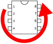
Using the meter you have you could start by checking that each chip is getting power ( normally 5V DC ). Most of the time it will be +5V on the last pin of chip ( as in pin 14 of a 14 pin package ), and diagonally opposite will be ground ( pin 7 of a 14 pin package ). In the common dual in-line package (DIP) pin numbering starts from the left side of a notch appearing on the top of the package and continues counterclockwise until it reaches the other side of the notch.
1668652229348.png
For some of the larger chips like the 6502 the power pins are in a different place, look up the data-sheet for each to see where VCC ( positive ) and ground are.
 

pball52998

Well-known member
Thank you for the info @lisa2 !

I'll check tomorrow afternoon with all the chips. New tools should be here Friday also to troubleshoot more. Excited to finally dive into using tools that always interested me but I never had a use for. Time to learn now!
 

pball52998

Well-known member
Okay so my oscilloscope should be here tomorrow.

I went through and measured all the voltages on the logic board.

Reseated every chip, and also sanded almost all of them.. Full of corrosion/rust I should have done first time around.

Most items in the center of the board (where the rust was) were the worst.

Measuring almost no voltage to start. After taking them out, sanding down the pins to nice and shiny:
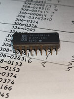
dirty legs.jpg

Clean legs:
clean legs.jpg
They started producing proper voltage! From .01 to 4.82 on all but about 5? I'll check again tomorrow.

Almost every IC is at 4.82v. There are a few that I find quite low at around 4-4.2v or none at all as stated.

Would you say anything falling at an average below 4.5 needs to be replaced?

Onto the meat and potatoes of this post.

I have been looking over the video logic again:

Along with page 122 here:

Please someone correct me or tell me if I'm going too deep into this.

I tried to cut my machine down to a 128k by taking out and only leaving row 2 of the 5v board. Every RAM chip is testing at 4.52 volts

Had a few RAM chips measure bad (no voltage or very low) so that's why I'm going with 128/known good.

So starting with tracking down no video (I actually get random dots on the screen now instead of blank!)
Tracking down White/Black video output. So RP4, Synch, RGB1,2,4,8, Porch

H3 produces RGB1,2,4,8.

Is that correct?

I've been trying to watch as many videos regarding apple ii and using a osilicope and tracking down video problems such as the one above, and ones from people such as adrians digital basement.

They seem to start in reverse. Going from the composite jack. "I don't see a ntsc signal. Lets move back to the next component."

In this instance, that would be G3/H3.

Testing pins 2, 7, 10, 15 should produce a ntsc signal/SOME signal on the scope? If we don't see it there, time to step back to G3, then to the chips before that?

Or go about a different testing method?

Such as page 122 in the manual.

Test H3, 2,7,10,15 if nothing:
See if same signal on pin 1 H3 is the same as G2 pin 12.

Trace pin 13 on G2 back to J3 pin 5

Pin J3 pin 2 -> H8 pin 6 -> F4 pin 13
J3 pin 4 -> F4 pin 13

F4 to E4/E5 11-14. (Combined the schematic and page 122 together)

E5/E4 talk to F2/E2 by doing:

15,16,17,1,2,3,4 -> 19,16,15,12,9,6,5,2

Seems I can probably also follow somewhere around page 298 with the flow charts.

Starting with G5 (video rom) pins either going high/low

Sorry for the ramble post. Just trying to get all my thoughts on paper to see the general consensus

We'll see what I can uncover!
 

joshc

Well-known member
Reseated every chip, and also sanded almost all of them.. Full of corrosion/rust I should have done first time around.
The problem is that the rust can go up the legs and inside the chip itself. I have no idea what chips were used on the Apple ///, but my guess is that most(all) of them are off the shelf and can hopefully be obtained still?
Had a few RAM chips measure bad (no voltage or very low) so that's why I'm going with 128/known good.
That seems like a sensible approach to me.

Eager to see the next update :)
 

pball52998

Well-known member
The problem is that the rust can go up the legs and inside the chip itself. I have no idea what chips were used on the Apple ///, but my guess is that most(all) of them are off the shelf and can hopefully be obtained still?
They can! I was surprised and relieved!

I've considered honestly doing a hail mary and replacing every damn chip except for the ROM/PROM chips

See page 330 for a big ol list . It's mostly ti IC chips that are still all around and I can get em for a buck a piece from the standard places.
 

CC_333

Well-known member
I've considered honestly doing a hail mary and replacing every damn chip except for the ROM/PROM chips
You might consider replacing the sockets too, since they're probably just as rusty as the ICs. Probably not super likely to fail if you clean them thoroughly enough, but if you're going to replace all the ICs anyway....

c
 

pball52998

Well-known member
You might consider replacing the sockets too, since they're probably just as rusty as the ICs. Probably not super likely to fail if you clean them thoroughly enough, but if you're going to replace all the ICs anyway....

c
You make a compelling argument!

There's been a trend of this thread of someone suggests something and it happens ;)

I'm easily convinced.

While getting my fiance to help me earlier she even hit me with the "can you desolder some of these so I can clean them better"

Fun fact. My keyboard encoder, decoder whatever the damn thing is was so rusted taking it out (first time was yesterday) took 8 or 10 legs with it and the socket was rusted through. Delicious.

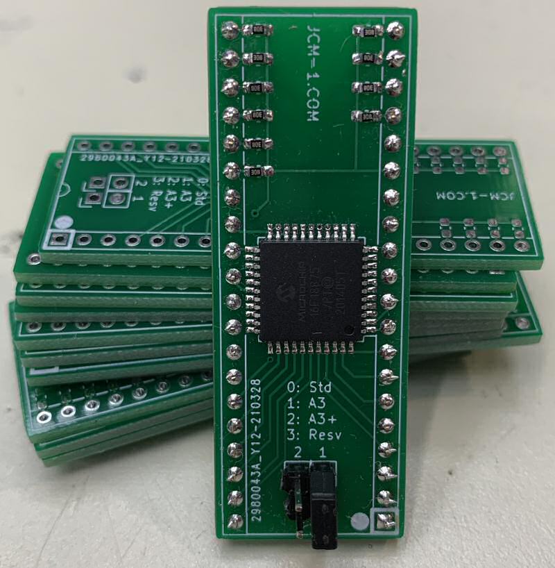
Gotta order a new keyboard IC from jcm-1.. thankfully those are still being repro'd!
 

bibilit

Well-known member
Had a few RAM chips measure bad (no voltage or very low)
As ram chip are not producing voltage but receiving one instead, your issue is probably before the chip itself, so consider tracking down the input voltages.
You might consider replacing the sockets too
Not a bad idea here, but a shorted or bad chip can drop the voltage enough to have that low 5 volt line (4.82 is probably still fine but 4.2 is not)
 

joshc

Well-known member
Is there a legit reason to keep everything socketed these days? I guess stuff can still fail but it seems like it should be less likely?
 

bibilit

Well-known member
legit reason to keep everything socketed these days
In my opinion yes, old PCBs are fragile, so stressing those more than required is not really a good idea.
a chip can fail more than once, and removing a chip from a socket is quicker and safer than using heat on old stuff
 

joshc

Well-known member
In my opinion yes, old PCBs are fragile, so stressing those more than required is not really a good idea.
a chip can fail more than once, and removing a chip from a socket is quicker and safer than using heat on old stuff
Fair point, I hadn't thought about the stress on the board.
 

pball52998

Well-known member
As ram chip are not producing voltage but receiving one instead, your issue is probably before the chip itself, so consider tracking down the input voltages
Question for you on this, the main one I found that had no voltage was right in the middle of the row. Basically every ram chip was 4.52, 4.52, etc etc then .1, then everything was 4.52 after

I replaced that chip and everything came to 4.52

Or are you referring to these chips only getting 4.52 on the board entirely when it probably should be closer to 4.8 range?

Edit: probably should word this better. I checked vcc/ground on every chip to get the voltages of them all. Sorry if stated something wrong in above post or and confusion
 
Last edited:

bibilit

Well-known member
are you referring to these chips only getting 4.52 on the board entirely when it probably should be closer to 4.8 range?

yes, 4.52 is too low in my opinion, even 4.8 is low you should be closer of 4.9 volts.

any hot chip ?
 

pball52998

Well-known member
Well for anyone in the future. I took the liberty of making a spreadsheet, with names from page 330/331 here in the reference manual

Comparing it to my board and trying to find every replaceable IC.

Includes where to buy them, colored ones that have multiples and price.

If I were to buy every IC except all the VIA/6502/ROM/PROMs etc without shipping it'd be right at $100.

This includes the keyboard encoder from jcm which is 26 though.

Not too bad.

I can't upload a straight xlsx (excel) file, so I put it in a zip.

Google sheets link too:

The only question I have, if someone takes a look at E12/13 and F12/13 the "DUAL 4 to 1 line MUX" & "DUAL 4 to 1 data MUX" are these the same?


According to the reference manual they're different part numbers
4 to 1 LINE: 308-0153
4 to 1 DATA: 306-0153

But they share the same CHIP/PART in the description.

If I can't find the problem with the osciliscope (I'll try but can't promise I know what I'm looking for!) I'll be trying to replace all these IC chips
 

Attachments

  • Apple iii IC.zip
    14.9 KB · Views: 1

pball52998

Well-known member
Have you tested the processor for reset and activity ?
Don't have anything to really test with till I get the oscilloscope unfortunately.. Is there really any other way to test it?

Unless I can put it in my c64.. but that was a 6510 which is just a modified 6502
 

pball52998

Well-known member
6510 has a different pin out, a regular 6502 won’t work.
Exactly.. yeah a few pins are different unfortunately. Only other thing I have that uses a 6502 is the 1541 disk drive. I could test it in there possibly


Scratch all that, mines not socketed like a lot of the 1541 drives are. Don't want to desolder it, just to test.. probably different anyways to some extent.
 
Last edited:
Top